Pressing fit machine for rolling bearing pedestal

A technology of rolling bearings and press-fitting machines, applied in metal processing, metal processing equipment, manufacturing tools, etc., can solve problems such as long time, hitting on the bearing surface, and difficult assembly, and achieve low production cost, high production efficiency, and concentricity Good results

Active Publication Date: 2013-07-03
山东开泰工业科技有限公司
View PDF9 Cites 21 Cited by
  • Summary
  • Abstract
  • Description
  • Claims
  • Application Information

AI Technical Summary

Problems solved by technology

[0002] A large number of rolling bearings are used to support the rotating shaft in the project. Since the inner ring of the rolling bearing and the shaft, the outer ring of the rolling bearing and the bearing seat often adopt an interference fit, for the bearing connection of a small size, the bearing is usually driven in manually with a hammer, which will cause assembly failure. When the force is uneven in the circumferential direction, the assembly is difficult, the time is long, and it will hit the bearing surface, which will damage the bearing and other parts in severe cases.
[0003] For this reason, someone has studied bearing installation equipment specifically for this problem, such as the schemes published in Chinese patents: CN201534273U and CN202367420U, in which two kinds of bearing press-fitting machines are announced, and an intermediate spindle fixing platform is required in these two kinds of press-fitting machines , in the actual operation process, because the coaxiality of the main shaft and the bearings at both ends is difficult to guarantee, the installation accuracy is reduced
The reason is that the positioning reference of the main shaft is on the main shaft fixed platform, and it is difficult to adjust the platform to make the three coaxial

Method used


Image

  • Pressing fit machine for rolling bearing pedestal
  • Pressing fit machine for rolling bearing pedestal
  • Pressing fit machine for rolling bearing pedestal

Examples


Embodiment Construction

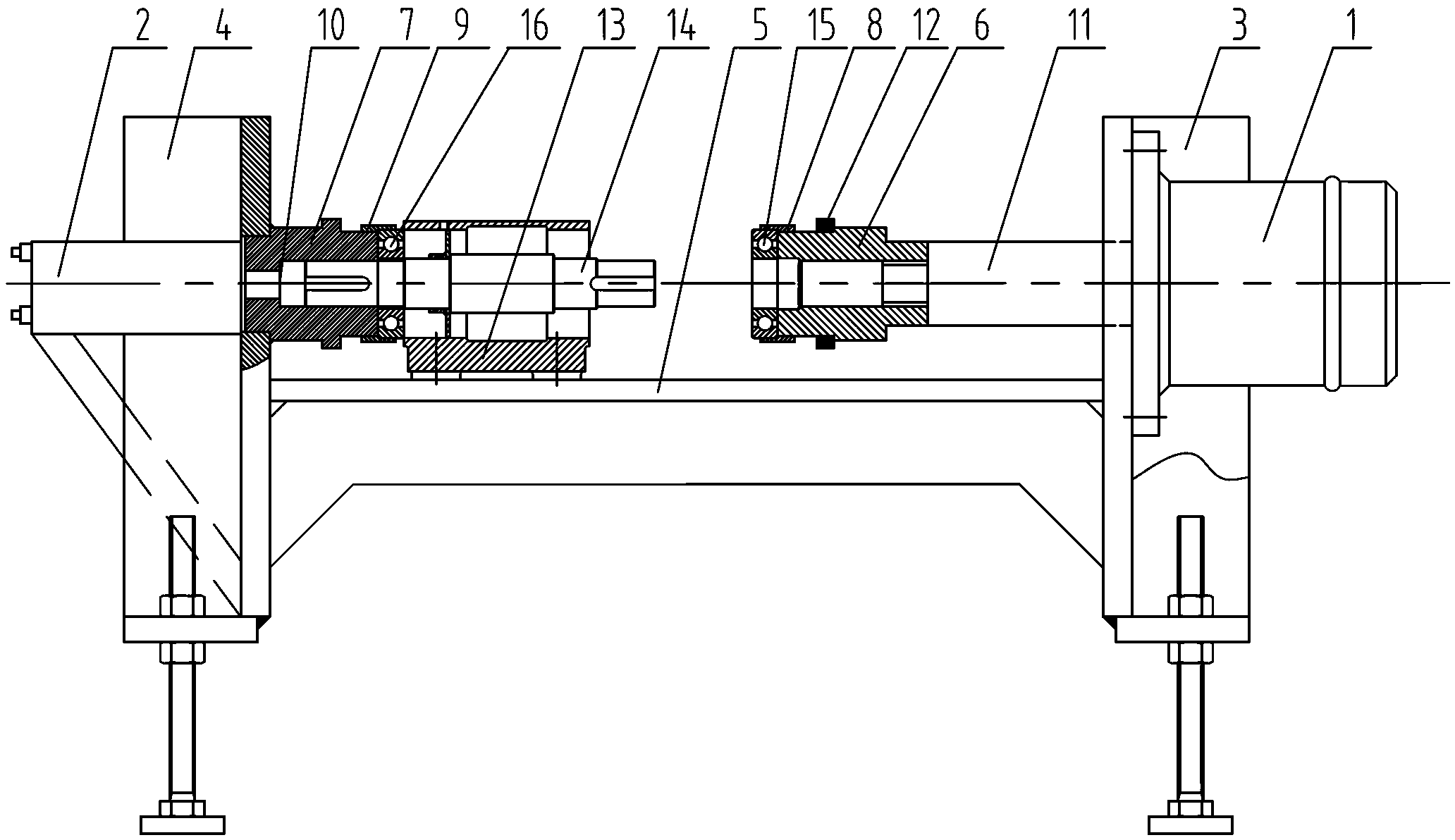
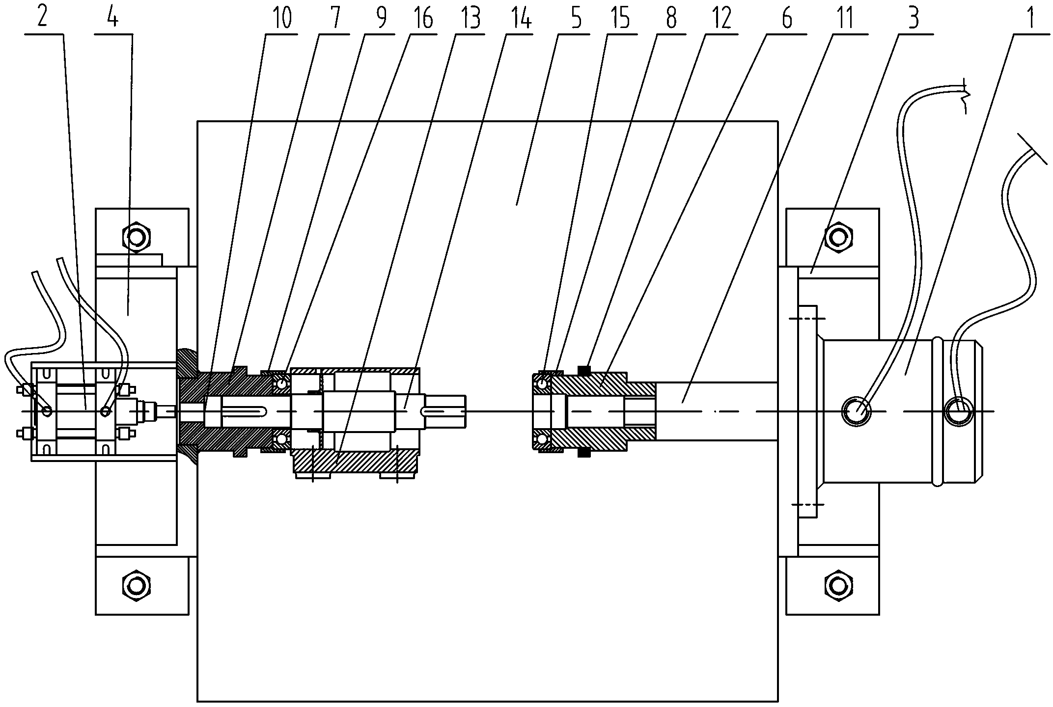
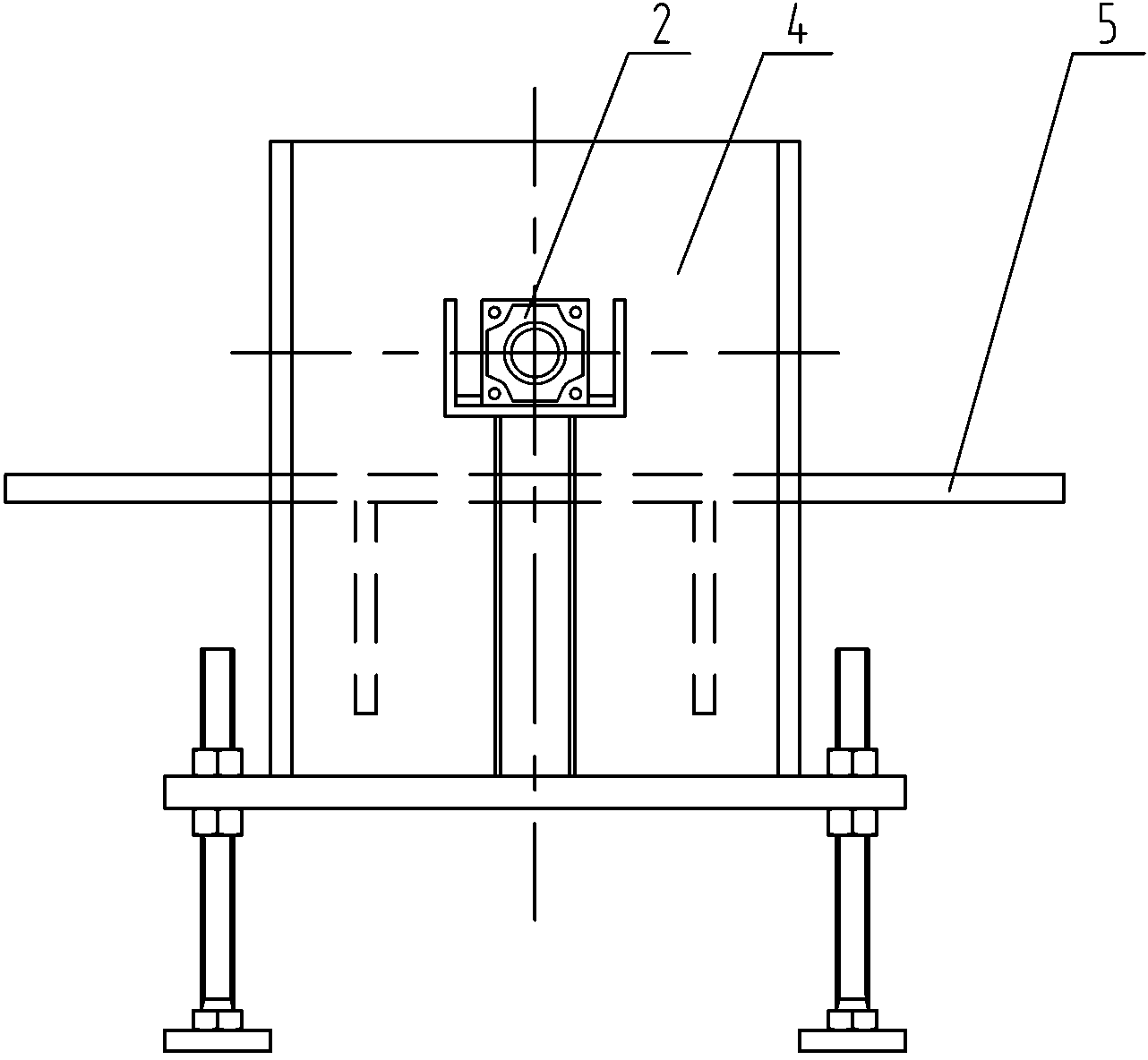
[0021] Such as figure 1 , figure 2 , image 3 and Figure 5 As shown, the rolling bearing mounting and pressing machine mainly includes a hydraulic cylinder 1, a pneumatic cylinder 2, a right support seat 3, a left support seat 4, a press mounting table 5, a main shaft movable guide sleeve 6, a main shaft fixed guide sleeve 7, the first bearing Guide collar 8, second bearing guide collar 9, spindle left moving positioning surface 10, hydraulic cylinder connection plate 11, press-fit ring 12.

[0022] The right support base 3 is fixed with a hydraulic cylinder 1, the piston rod of the hydraulic cylinder 1 stretches out horizontally to the left, the front end of the piston rod is fixed with a piston rod connector 11, and the left end of the piston rod connector 11 is threadedly connected with a main shaft movable guide sleeve 6, The main shaft movable guide sleeve 6 is processed with a stepped inner hole, the right end of the main shaft to be loaded into the bearing can go d...


PUM


Abstract

The invention provides a pressing fit machine for a rolling bearing pedestal. A support platform consists of a left support base, a right support base and a pressing fit table, and the heights of the left support base and the right support base can be respectively adjusted, so that the levelness of the pressing fit table can be guaranteed; and the right support base is fixedly provided with a hydraulic cylinder, a piston rod of the hydraulic cylinder horizontally and leftwards extends, the front end of the piston rod is fixedly provided with a piston rod connecting piece, the left end of the piston rod connecting piece is provided with a first bearing installing part, and the left support base is a main shaft installing part. When the pressing fit machine is used, a left-side bearing and a main shaft workpiece are directly arranged on a main shaft fixed guide sleeve, the left-side bearing and the main shaft workpiece are coaxial with each other, and the pressing fit machine can be better positioned, is free from adjustment, and can be used only by adjusting the coaxial relationship between a right-end bearing and the main shaft, so that one adjustment can be reduced, and the assembly efficiency and precision can be improved. Meanwhile, the bearing in the device is directly clamped into a bearing guide lantern ring, so that the pressing fit machine can be conveniently and quickly used.

Description

technical field [0001] The invention relates to a pressure assembling machine, in particular to a pressure assembling machine for loading a rolling bearing into a bearing seat. Background technique [0002] A large number of rolling bearings are used to support the rotating shaft in the project. Since the inner ring of the rolling bearing and the shaft, and the outer ring of the rolling bearing and the bearing seat are often used for interference fit, for the bearing connection of small size, the bearing is usually driven in manually with a hammer, which will cause assembly problems. When the force is uneven in the circumferential direction, the assembly is difficult, the time is long, and it will hit the bearing surface, which will damage the bearing and other parts in severe cases. [0003] For this reason, someone has studied bearing installation equipment specifically for this problem, such as the schemes published in Chinese patents: CN201534273U and CN202367420U, in wh...

Claims


Application Information

Patent Timeline
Patent Type & Authority Applications(China)
IPC IPC(8): B23P19/027
Inventor 张来斌颜景山韩春师张亚楠
Owner 山东开泰工业科技有限公司
Why Eureka
Try Eureka