
Implanted and grouted compound pile and construction method

A combined pile and grouting technology, which is applied in the direction of sheet pile walls, foundation structure engineering, construction, etc., can solve the problems of limited side friction resistance of the pile body and affect the quality of adjacent piles, etc., to achieve small soil squeezing effect and save machinery The amount of use, the effect of improving the bearing capacity of the foundation

Active Publication Date: 2013-07-03
ZHEJIANG TIANRUN CONSTR
View PDF10 Cites 21 Cited by
  • Summary
  • Abstract
  • Description
  • Claims
  • Application Information

AI Technical Summary

Problems solved by technology

[0006] To sum up, the construction of prefabricated tubular piles is convenient, but the lateral frictional resistance of the piles is limited, most of them are end-bearing piles, and the usual pile construction is likely to affect the pile quality of adjacent piles

Method used


Image

  • Implanted and grouted compound pile and construction method
  • Implanted and grouted compound pile and construction method
  • Implanted and grouted compound pile and construction method

Examples


Embodiment Construction

[0041] Technical requirements for welding construction, technical requirements for connection between Y-shaped wing plate and pipe pile, technical requirements for stacking and hoisting of pipe piles, technical requirements for drilling soil, technical requirements for grouting body mix ratio design and construction, solidified backfill soil mix ratio design and construction Technical requirements, etc., will not be repeated in this embodiment, but focus on the embodiment of the structure involved in the present invention.

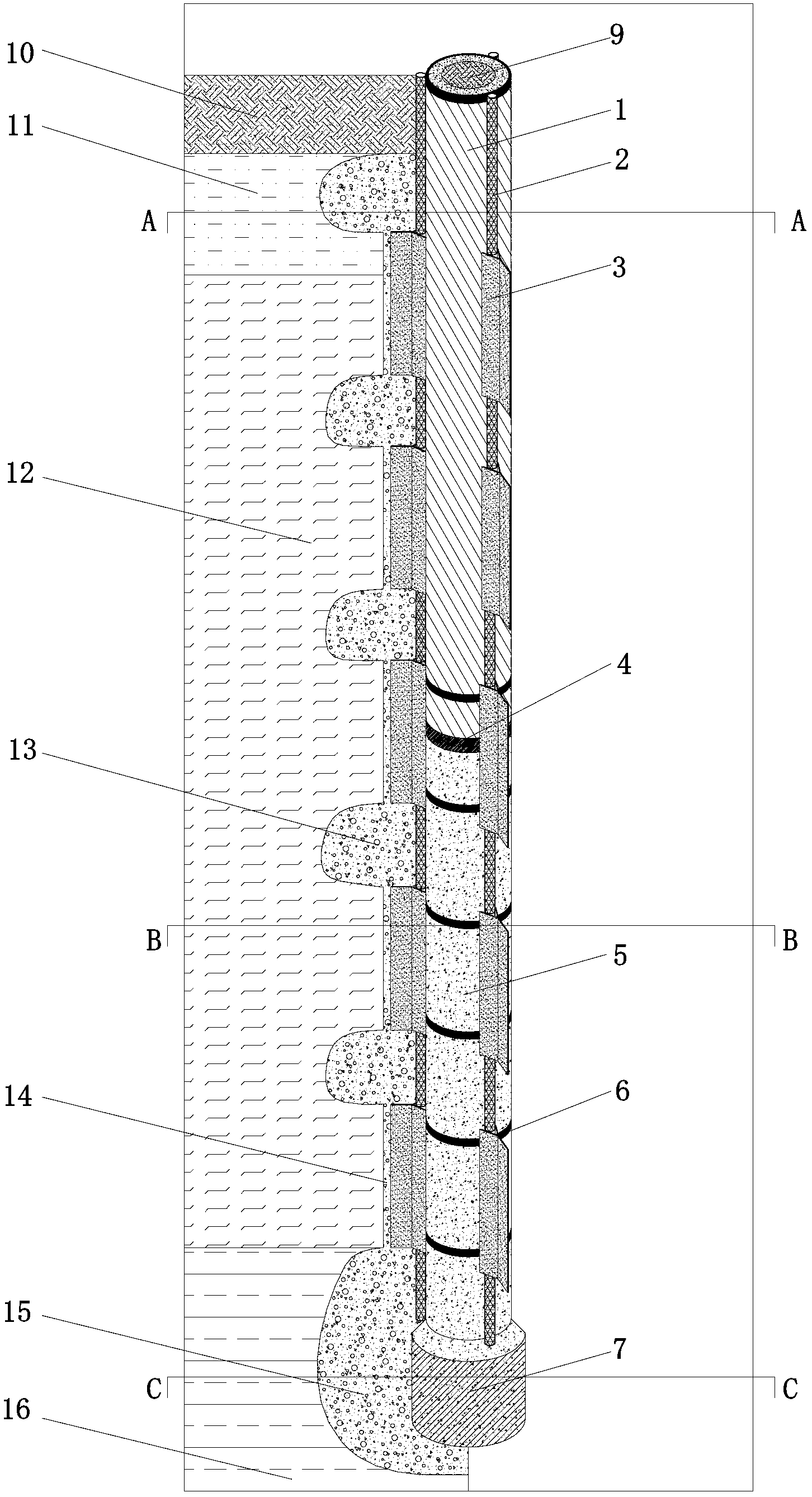
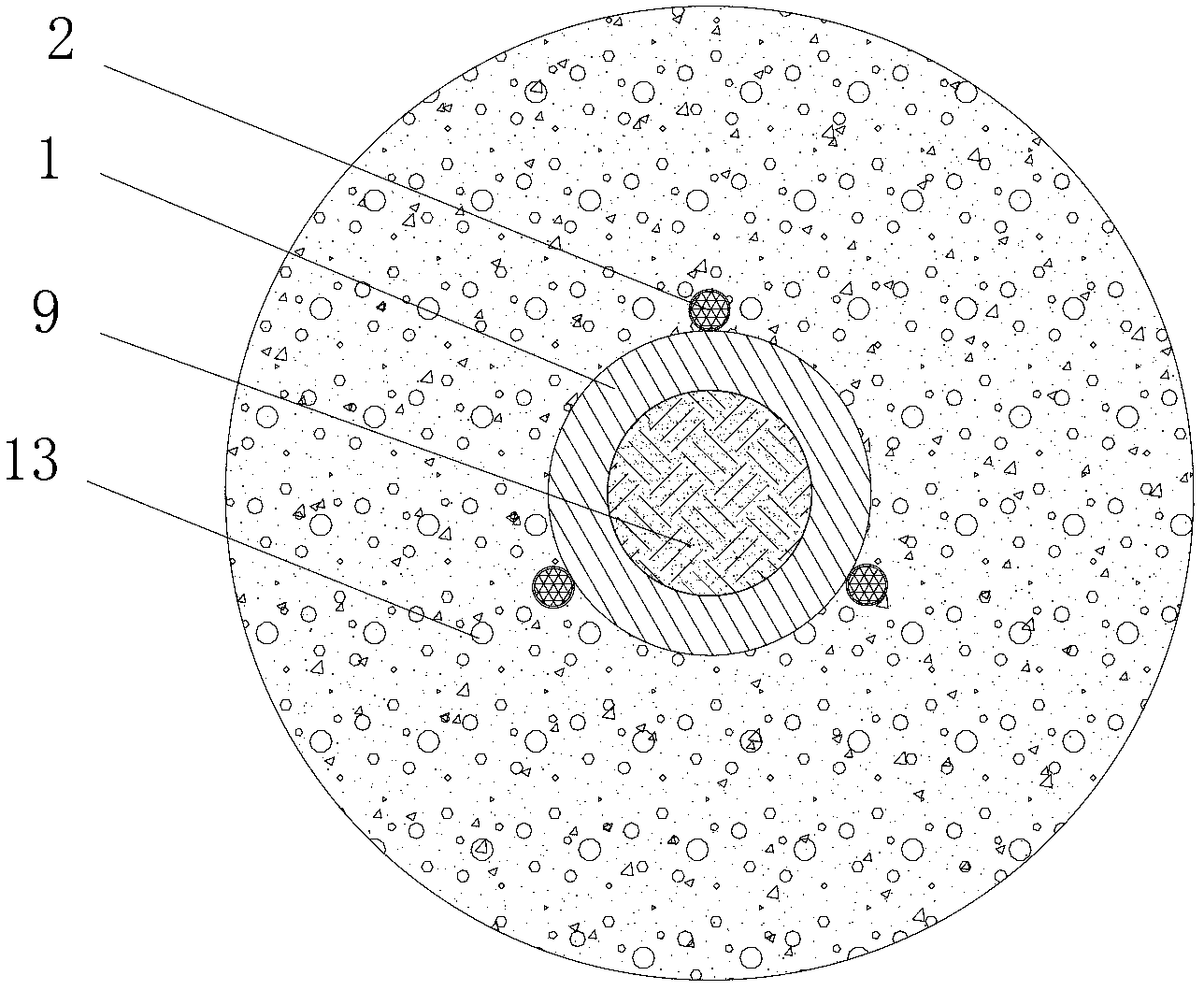
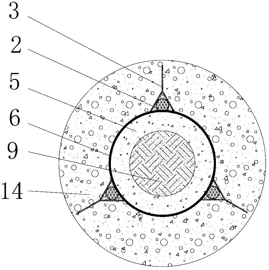
[0042] figure 1 It is a schematic diagram of the structure of the implanted grouting composite pile of the present invention, figure 2 yes figure 1 The sectional view of the Y-shaped wing plate along the A-A line, image 3 yes figure 1 A sectional view of the Y-shaped wing plate and the Y-shaped wing plate fixing ring along the line B-B, Figure 4 yes figure 1 Cut along the line C—C to the sectional view of the prefabricated expanding head, refer...


PUM

PropertyMeasurementUnit
Thicknessaaaaaaaaaa
The inside diameter ofaaaaaaaaaa

Abstract

The invention relates to an implanted and grouted compound pile which mainly comprises a precast tubular pile, Y-shaped wing plates, solidified backfill soil, pile side grouting reinforcing bodies, high pressure grouting squeezing bodies, a pile bottom precast enlarged head and a pile bottom high pressure grouting enlarged head. The precast tubular pile is formed by combining and connecting a plurality of sections of tubular piles with one or various pile diameters; the bottom of the precast tubular pile is provided with the precast enlarged head; the Y-shaped wing plates are uniformly distributed outside the tubular pile in the ring direction; high pressure grouting tubes pass through cavities between the Y-shaped wing plates and the tubular pile and the positions of grouting tube orifices are adjustable; the high pressure grouting squeezing bodies are formed by continuously grouting at the designed positions at high pressure; and the solidified backfill soil is back filled into a cavity inside the precast tubular pile and the residual solidified soil is paved on the construction site. According to the invention, the enlarged pile head is formed at the bottom of the tubular pile and the grouting reinforcing bodies and the high pressure grouting squeezing bodies are formed outside the tubular pile, so that bearing capacity of the soil in different positions around the pile can be sufficiently played; and a drilling and earth borrowing technology is adopted to form a hole, and a soil compaction effect is small. Moreover, the invention further discloses a construction method of the implanted and grouted compound pile.

Description

technical field [0001] The invention relates to an implanted grouting composite pile and a construction method, in particular to a method that can form various grouting reinforcements on the side of the pile, can fully exert the bearing capacity of the soil at different positions around the pile, and reduce soil extrusion during pile construction. Effect of the new pile structure and its construction method. It belongs to the field of foundation treatment and is suitable for foundation treatment projects of municipal and construction projects with poor geological conditions and adjacent to tall buildings. Background technique [0002] my country has a vast territory and ever-changing geological conditions. Some buildings built on soft soil foundations often have problems such as large settlement, obvious differential settlement, and insufficient bearing capacity, which in turn affects the normal use and safety performance of the buildings. If municipal and high-rise buildin...

Claims


Application Information

Patent Timeline
IPC IPC(8): E02D5/38E02D5/44E02D5/48E02D5/52E02D15/04
Inventor 姜平平叶喆宏章红江吴雪凤
Owner ZHEJIANG TIANRUN CONSTR
Learn More