Vertical rainwater zoning drainage system

A drainage system and rainwater technology, which is applied to waterway systems, drainage structures, and sewage discharge, can solve the problems of lack of rainstorm prevention and control measures and insufficient understanding of the severity of rainstorm and waterlogging disasters, so as to prevent and control waterlogging disasters, ensure personal and property safety, and save money. The effect of manpower and material resources consumption

Active Publication Date: 2013-07-03
中国市政工程西北设计研究院有限公司
View PDF5 Cites 8 Cited by
  • Summary
  • Abstract
  • Description
  • Claims
  • Application Information

AI Technical Summary

Problems solved by technology

[0005] 3. Insufficient understanding of the severity of rainstorm and waterlogging disasters. The prevention and control of rainstorm disasters are basically lagging passive transmission, emergency rescue, and lack of prevention and control measures before the rainstorm

Method used


Image

  • Vertical rainwater zoning drainage system
  • Vertical rainwater zoning drainage system
  • Vertical rainwater zoning drainage system

Examples


Embodiment 1

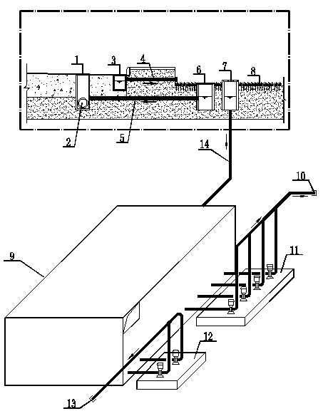
[0042] Embodiment 1: as figure 1 Shown: a rainwater vertical partition drainage system, including a sunken green area 8, rainwater removal facilities in the low area and rainwater removal facilities in the high area; the rainwater removal facilities in the low area include municipal rainwater inspection wells 1, road rainwater installed on the side of the road Outlet 3, the diffuse rainwater outlet 6 located in the concave green space 8; the rainwater drainage facilities in the high area include the overflow rainwater outlet 7 located in the concave green space 8, the sump 9 and the emergency rainwater discharge pump set 11, the overflow type The rainwater outlet 7 is connected to the sump 9 through the rainwater pipe 14 in the high area, the sump 9 is connected to the emergency rainwater discharge pump unit 11, and the output port 10 of the emergency rainwater drainage pump unit 11 is connected to the urban flood drainage ditch or ravine or depression; municipal rainwater ins...

Embodiment 2

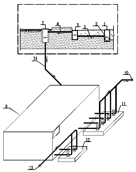
[0045] Embodiment 2: as figure 2 Shown: a rainwater vertical partition drainage system, including conventional rainwater removal facilities, the conventional rainwater removal facilities include municipal rainwater inspection wells, municipal rainwater pipes 2, road stormwater outlets 3 and rainwater branch pipes 5; the rainwater vertical partition drainage system also includes high District rainwater removal facilities; high-level rainwater removal facilities include overflow stormwater outlet 7, sump 9 and emergency rainwater discharge pump unit 11; The rainwater outlet 7 is connected to the road rainwater outlet 1 through the overflow connecting pipe 4, the overflow rainwater outlet 7 is connected to the sump 9 through the high area rainwater pipe 14, the sump 9 is connected to the emergency rainwater discharge pump group 11, and the emergency rainwater discharge pump The output port 10 of the group 11 communicates with the urban flood drainage ditch or ravine or depressio...


PUM


Abstract

The invention discloses a vertical rainwater zoning drainage system which comprises a concave green area, a low-zone rainwater disposal facility and a high-zone rainwater disposal facility, wherein the low-zone rainwater disposal facility comprises a municipal rainwater inspection well, a road gully on the side of a road, and a sheetflood gully in the concave green area; the high-zone rainwater disposal facility comprises an overflow gully in the concave green area, a water collecting basin and an emergency rainwater discharge pump set; the overflow gully is connected with the water collecting basin; the water collecting basin is connected with the emergency rainwater discharge pump set; a delivery outlet of the emergency rainwater discharge pump set is communicated with an urban flood drainage channel or a ravine or a depression; the municipal rainwater inspection well is communicated with the sheetflood gully; the road gully is connected with an overflow communicating pipe; an outlet of the overflow communicating pipe is communicated with the concave green area; the overflow gully is designed in the specification that P is greater than set P; and the sheetflood gully is designed in the specification that P is less than or equal to set P. The system nips in the bud, can effectively prevent and treat a waterlogging disaster generated by rainstorm, can ensure personal and property safety, and changes passive salvation after the disaster into positive prevention and treatment before the disaster.

Description

technical field [0001] The invention belongs to the technical field of rainstorm and waterlogging disaster prevention and control in low-lying areas of cities and towns, in particular to a rainwater vertical partition drainage system. Background technique [0002] In the past two years, the climate has been abnormal, with frequent rainstorms and severe waterlogging in low-lying urban areas such as underground buildings, sunken squares, and sunken sections of road overpasses, which can cause pedestrians to be blocked and traffic to be paralyzed, and serious casualties and major property losses . In order to rescue the waterlogging disaster, it consumes a lot of manpower and financial resources. With regard to its reason, mainly contain following deficiency and insufficiency: [0003] 1. The rainwater part in the outdoor drainage design specification is more focused on conventional rainfall (P≤P within the design return period range) 设 ) exclusion, for heavy rain (P≥P 设 gr...

Claims


Application Information

Patent Timeline
Patent Type & Authority Applications(China)
IPC IPC(8): E03F1/00E03F5/00E03F5/04E03F5/22
CPCY02A20/20
Inventor 刘文林陈海龙陈致明魏惠荣肖云
Owner 中国市政工程西北设计研究院有限公司
Why Eureka
Try Eureka