Annular porous nano magnetic bead separator and mounting method thereof

A technology of nano-magnetic beads and separators, which is applied in the preparation of test samples and other directions, can solve the problems of low separation efficiency, low magnetic permeability, and difficulty in clamping, and achieves the effects of high magnetic permeability and less loss of magnetic permeability.

Active Publication Date: 2013-07-03
SOUTH CHINA AGRI UNIV
View PDF4 Cites 7 Cited by
  • Summary
  • Abstract
  • Description
  • Claims
  • Application Information

AI Technical Summary

Problems solved by technology

[0006] 1. When multi-point (multi-sample) processing is required, because the device cannot be closed, the magnetic field of the magnets at both ends leaks out. When it is used for sample processing, the effect is significantly weakened. Therefore, the magnetic bead separator using cubic permanent magnets is suitable for Magnet utilization is low
Especially the two outermost test tube holes have only one-sided excitation, and the separation effect of one-sided excitation is poor, so these two test tube holes are basically not used in the separation test
[0007] 2. The separation efficiency is low, the separation efficiency using 30nm magnetic beads is only 75%
[0009] 4. The material of the metal sheet is iron, and its magnetic permeability is low. When it is used to transmit a magnetic field, the effect is not ideal
[0010] 5. Due to the use of cubic permanent magnets, it is inconvenient for the magnetic bead separator to realize rotation and vibration, which is not conducive to the combination of the magnetic bead separator and other pre-treatment links, and is not conducive to the formation of magnetic separation and mixing automation.
Therefore, this special fixture needs to be customized, and the clamping is difficult, and the assembly of the magnetic bead separator is difficult

Method used


Image

  • Annular porous nano magnetic bead separator and mounting method thereof
  • Annular porous nano magnetic bead separator and mounting method thereof
  • Annular porous nano magnetic bead separator and mounting method thereof

Examples


Embodiment Construction

[0042] The present invention will be further described in detail in conjunction with the accompanying drawings and specific embodiments.

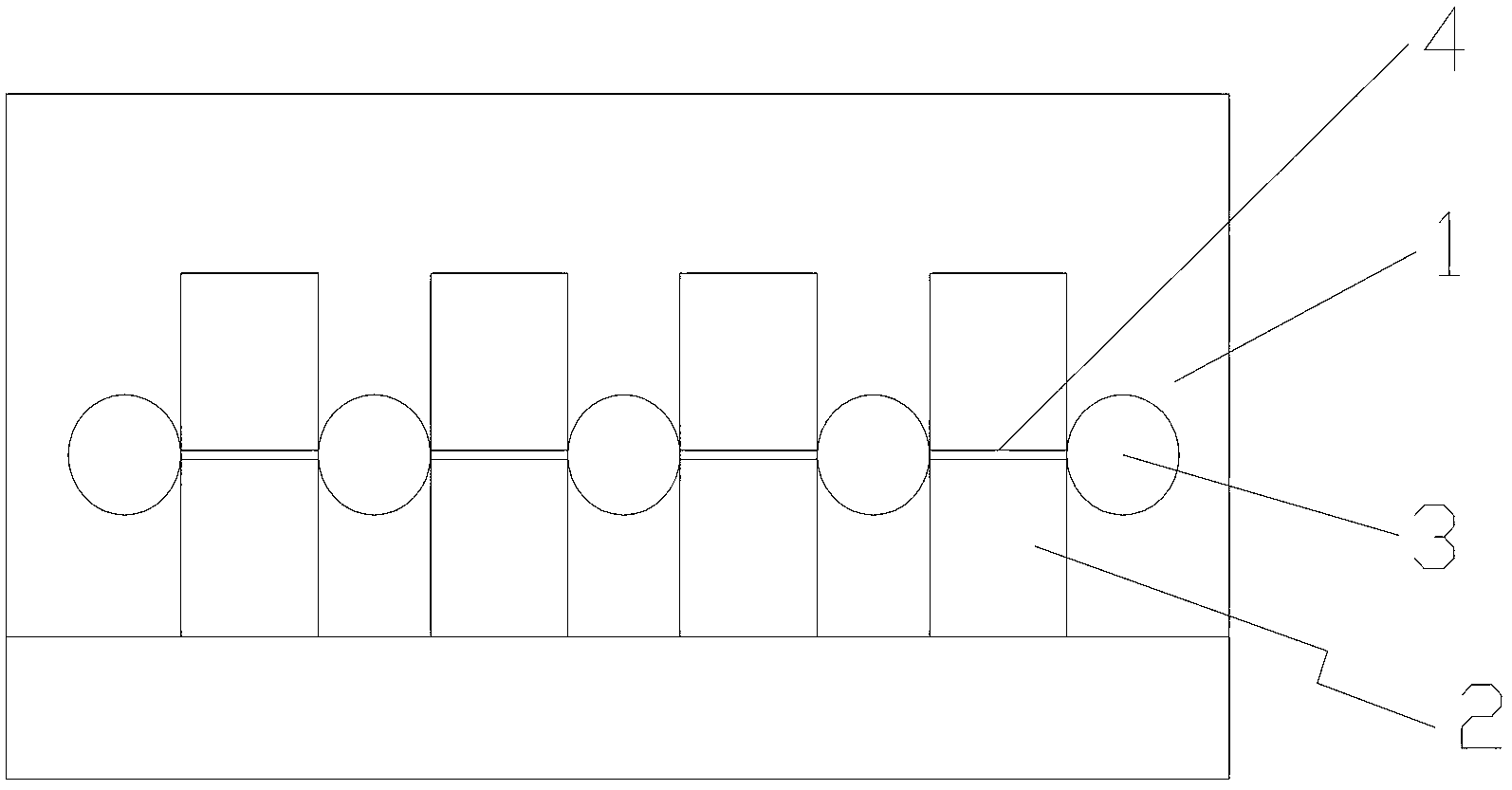
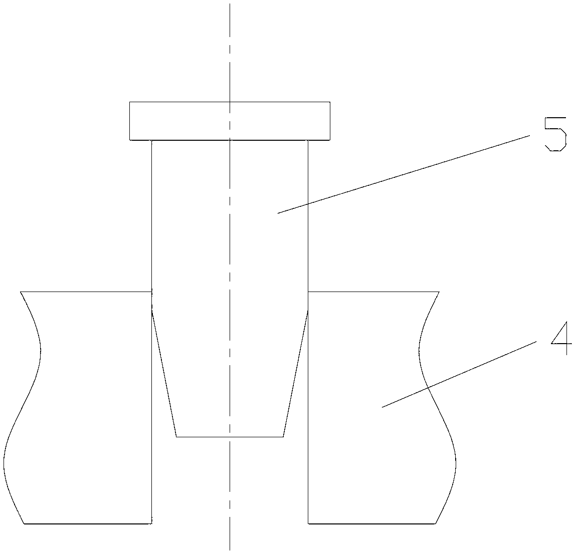
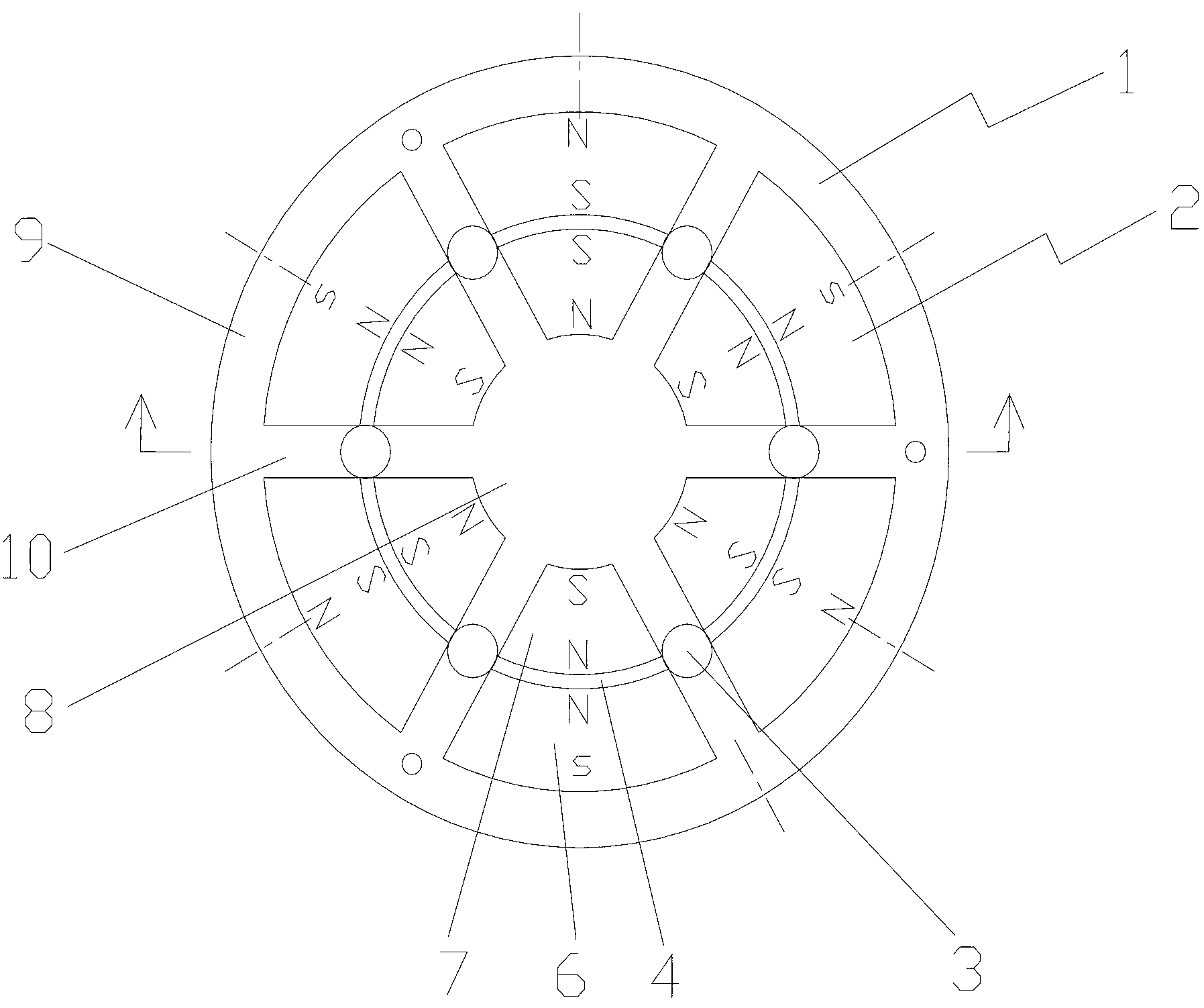
[0043] The annular porous nano-magnetic bead separator includes: a shell, six magnet groups, six metal sheets and two plexiglass plates.

[0044] The shell includes: a circular part, a ring part and six partition parts, and the circular part, the ring part and the partition part are integrally formed. The circular portion is located at the center of the annular portion. The separator part is located between the circular part and the annular part, and its length direction is consistent with the radial direction, and the six separator parts are evenly distributed along the circumference. The circular part, the ring part and the partitions on both sides surround a tile-shaped cavity for accommodating the magnet group. Test tube holes for placing test tubes are arranged on the partition part.

[0045] The magnet group includes tile-shaped la...


PUM

PropertyMeasurementUnit
separationaaaaaaaaaa

Abstract

The invention relates to an annular porous nano magnetic bead separator which comprises a casing and magnet groups, wherein each magnet group adopts a tile shape, and the number of the magnet groups is an even number; the magnet groups are arranged in an accommodating cavity which corresponds to the shape of the magnet groups and is arranged in the casing in an annular manner; a tube hole for accommodating a tube is arranged on the casing between every two adjacent magnet groups; and the polarities of poles of every two magnet groups are contrary. The invention further relates to a mounting method of the annular porous nano magnetic bead separator. The annular porous nano magnetic bead separator and the mounting method thereof have the advantages that the utilization rate of magnets and the tube holes are effectively improved, the separation efficiency is improved, and the annular porous nano magnetic bead separator can be assembled easily. The annular porous nano magnetic bead separator belongs to the technical field of nano magnetic bead separation devices.

Description

technical field [0001] The invention relates to a nano-magnetic bead separation device, in particular to an annular porous nano-magnetic bead separator and an installation method thereof. Background technique [0002] Nano-magnetic bead separation technology has been widely used in many fields involving the detection of microorganisms and chemical targets. Purification, dilution, etc., are a pretreatment method for the detection and analysis of microbial and chemical targets. The principle is: the surface of the magnetic beads modified with the target microbial antibody is sensitive to the external magnetic field due to the specific reaction of the antibody antigen to form a magnetic bead microbial conjugate; the magnetic bead microbial conjugate is adsorbed, and free impurities are removed, thereby achieving the target material purification and enrichment. [0003] For a small amount of microorganisms or chemical targets to be captured and separated from complex backgroun...

Claims


Application Information

Patent Timeline
Patent Type & Authority Applications(China)
IPC IPC(8): G01N1/34G01N1/40
Inventor 刘洪山罗锡文莫嘉嗣林杰斯
Owner SOUTH CHINA AGRI UNIV
Why Eureka
Try Eureka