Electromagnetic interference detecting device and method for pinhole detecting equipment

A technology for detecting equipment and electromagnetic interference, which is applied in the direction of measuring devices, measuring electricity, and measuring electrical variables, etc. It can solve problems such as bad electromagnetic interference, the influence of pinhole detection equipment, and difficulty in judging detection equipment, so as to improve the stable operation of equipment The effect of improving the efficiency, improving the ability of anti-electromagnetic interference, and improving the detection ability of equipment

Active Publication Date: 2013-07-03
BAOSHAN IRON & STEEL CO LTD
View PDF4 Cites 4 Cited by
  • Summary
  • Abstract
  • Description
  • Claims
  • Application Information

AI Technical Summary

Problems solved by technology

[0004] Due to the presence of a large number of motors and strong electrical equipment on the production site, the electromagnetic interference in the surrounding environment will be relatively harsh when the testing equipment is installed, which may affect the pinhole testing equipment and cause false alarms of defects, etc.
At the same time, the size of pinholes detected by pinhole detection equipment is generally accurate to the micron level. In an online detection environment, it is difficult to judge pinholes of this order of magnitude with the naked eye.
Therefore, it is difficult to judge whether the pinhole detected by the detection equipment is a real pinhole defect or a false alarm caused by electromagnetic interference
In this case, equipment use and maintenance personnel often use experience to judge, lacking the necessary scientific basis

Method used


Image

  • Electromagnetic interference detecting device and method for pinhole detecting equipment
  • Electromagnetic interference detecting device and method for pinhole detecting equipment
  • Electromagnetic interference detecting device and method for pinhole detecting equipment

Examples


Embodiment Construction

[0027] The present invention will be further described below in conjunction with the accompanying drawings and specific embodiments.

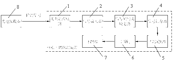
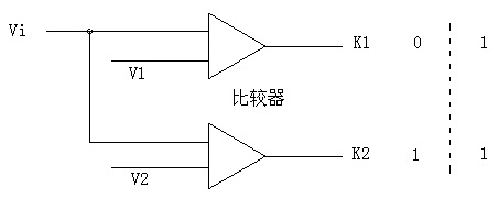
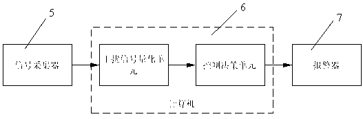
[0028] see figure 1 , an electromagnetic interference detection device for pinhole detection equipment, comprising a photoelectric isolation circuit 1, a signal amplifier 2, a signal encoding comparison circuit 3, a signal latch 4, a signal collector 5, a computer 6 and an alarm 7; After the signal is input into the interference detection device, it enters the signal amplifier 2 through the photoelectric isolation circuit 1, and the output of the signal amplifier 2 is connected to the signal coding comparison circuit 3. The signal coding comparison circuit 3 includes two comparators, and the detection signal is input into the two comparators in parallel. The input terminal of the comparator, the reference voltage of the input terminal of the comparator is the threshold voltage, the threshold voltage V2 of one comparator is equal to the threshol...


PUM


Abstract

The invention discloses an electromagnetic interference detecting device and a method for pinhole detecting equipment. A detection signal is input into an interference detecting device and enters a signal amplifier (2) through an optoelectronic isolation circuit (1), an output of the signal amplifier is connected with a signal encoding comparing circuit (3), an output of the signal encoding comparing circuit is connected with a signal latch (4), the signal in the signal latch is collected by a signal collector (5) and transmitted to a computer (6), the signal is processed by the computer and output, and the output signal is connected with an alarm (7). According to the electromagnetic interference detecting device and the method for the pinhole detecting equipment, the detection signal is collected, processed, converted into a grading digital signal, sent to the computer and processed so that an interference impulse sequence chart can be displayed, an electromagnetic interference frequency can be analyzed and calculated, and the electromagnetic interference which is over large is alarmed. The electromagnetic interference detecting device and the method for the pinhole detecting equipment can conveniently achieve detection of an environmental electromagnetic interference signal and judgment of interference degree so that a working state of the detecting equipment and the reliability of detecting data can be judged.

Description

technical field [0001] The invention relates to the technical field of photoelectric detection, in particular to an electromagnetic interference detection device and method for pinhole detection equipment. Background technique [0002] Under the current situation, there are often many tiny holes with the unit of micron appearing on the strip steel during the strip rolling process. The appearance of these holes seriously affects the quality of the strip, but it is difficult to find them with the naked eye. It is necessary to use testing equipment to detect them. Perform online real-time detection. [0003] Most of the existing pinhole detectors for pinhole detection of cold-rolled thin strips adopt the principle of photoelectric conversion. A fluorescent or laser light source is installed above the strip, and a photoelectric receiving module is installed below to realize the detected pinhole optical signal to the electric Efficient transitions between signals. After...

Claims


Application Information

Patent Timeline
Patent Type & Authority Applications(China)
IPC IPC(8): G01R31/00
Inventor 何永辉王康健
Owner BAOSHAN IRON & STEEL CO LTD
Why Eureka
Try Eureka