Camera night vision illuminating system and control method thereof

A lighting system and camera technology, applied in the field of night vision lighting, can solve the problems of large light waste, hidden dangers, and inability to use one light for multiple purposes, and achieve the effects of easy processing and post-assembly, meeting the needs of the field of view, and high effective utilization

Active Publication Date: 2013-07-03
TIANJIN YAAN TECH CO LTD
View PDF9 Cites 9 Cited by
  • Summary
  • Abstract
  • Description
  • Claims
  • Application Information

AI Technical Summary

Problems solved by technology

[0002] At present, with the continuous improvement of people's demand for night vision lighting, various night vision lighting equipment emerges in an endless stream. Generally speaking, there are the following trends: 1) fixed-focus infrared lighting products, the divergence angle of the light emitted by this product is fixed, Can not take into account the far and near lighting and meet the needs of the camera's field of view at the same time; 2) Infrared products with multi-angle LED lights that can be turned on in sections. Larger waste of light; 3) Zoom infrared products, this category has two branches, one is zoom LED products, the effective utilization rate of light of this kind of products is low, the optical path design is more complicated, and it is not enough for long-distance lighting. The overall cost performance is not high; the second is the variable focus laser products, which are generally Class 4 laser products in order to ensure the lighting distance, lack of necessary safety protection measures, and have potential safety hazards. At the same time, the range of divergence angles is difficult to meet the field of view requirements of wide-angle lenses

Method used


Image

  • Camera night vision illuminating system and control method thereof
  • Camera night vision illuminating system and control method thereof
  • Camera night vision illuminating system and control method thereof

Examples


Embodiment Construction

[0029] In order to enable those skilled in the art to better understand the technical solutions of the present invention, the present invention will be further described in detail below with reference to the accompanying drawings and embodiments.

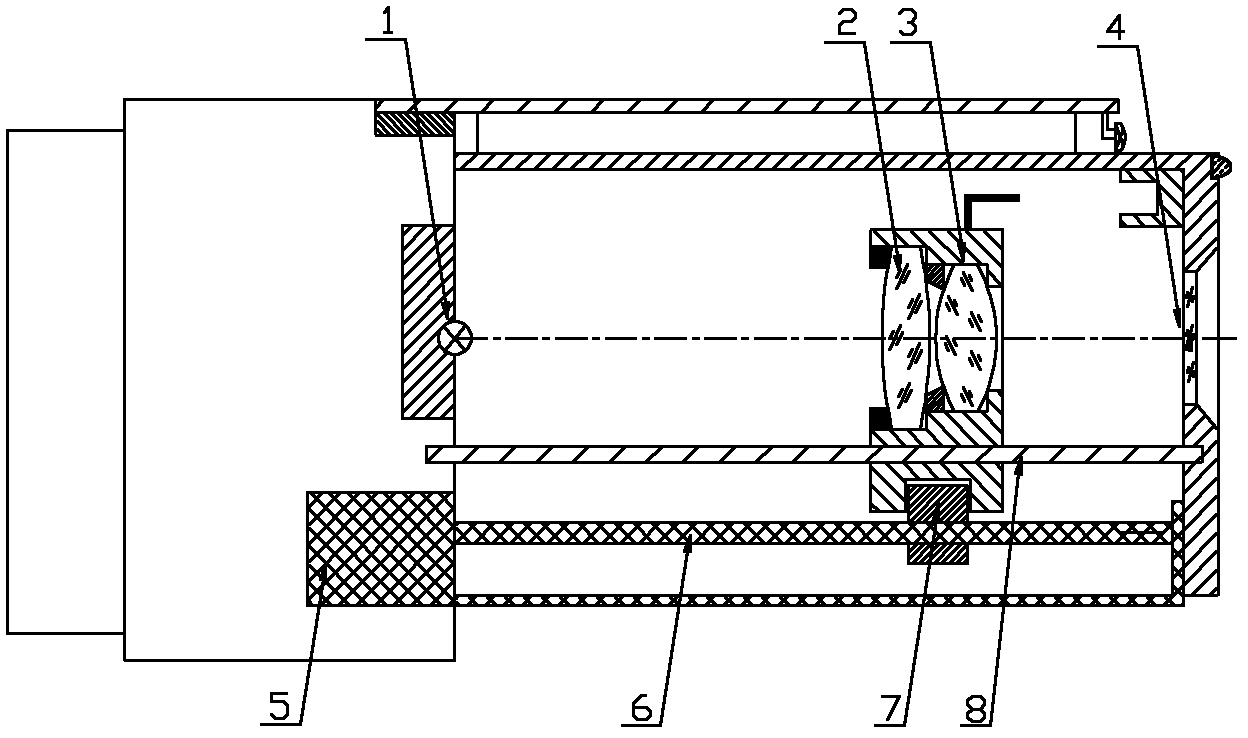
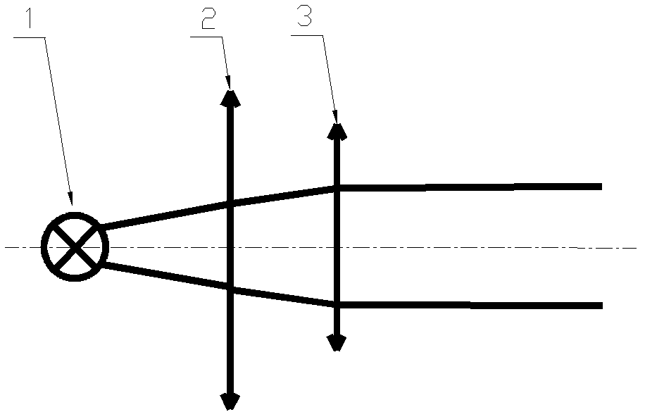
[0030] Such as figure 1 As shown, the camera night vision lighting system of the present invention includes a control module and a power module connected to the control module, a photoresistor, an optocoupler switch, a stepping motor, and a laser ranging sensor; the power module is connected to the infrared light source, and the infrared light source front end A variable-angle lens is provided, and the stepping motor is connected with the variable-angle lens.

[0031] The power module is an adjustable constant current source power module, which provides power for the entire night vision lighting system; the photoresistor monitors the light intensity of the external environment, and transmits the monitoring information to the control modul...


PUM


Abstract

The invention discloses a camera night vision illuminating system and a control method thereof, wherein the camera night vision illuminating system is high in optical utilization rate, large in divergence angle adjustment scope, and capable of achieving attention to both short-range and long-range targets. The camera night vision illuminating system comprises a control module, a power module, a light dependent resistor, an optical coupling switch and a stepping motor, wherein the power module, the light dependent resistor, the optical coupling switch and the stepping motor are connected with the control module. The power module is connected with an infrared source, an angle changing lens is arranged at the front end of the infrared source, and the stepping motor is connected with the angle changing lens. The camera night vision illuminating system is characterized by further comprising a laser distance measuring sensor which is connected with the control module. The night vision illuminating system is big in light-out divergence angle scope, capable of achieving attention to both short-range and long-range targets and meeting requirements for a camera market, high in optical effective utilization rate, simple in optical path design, good in long-distance illumination effects, low in cost, and easy to process and assemble in the later stage. Through adoption of a laser ranging linkage angle changing mode, the camera night vision illuminating system is safe, reliable, and capable of effectively avoiding potential safety hazards of laser products.

Description

Technical field [0001] The invention relates to the field of night vision lighting in the field of video surveillance, and in particular to a camera night vision lighting system and a control method thereof. Background technique [0002] At present, as people's demand for night vision lighting continues to increase, various night vision lighting equipment are emerging in an endless stream. In general, there are mainly the following trends: 1) Fixed-focus infrared lighting products, the divergence angle of this kind of product is constant, Can't take into account the needs of far and near lighting and the camera's field of view at the same time; 2) Infrared products with multi-angle LED lights turned on in sections, although this type of product can take into account the needs of far and near lighting, it requires multiple wicks and cannot be used for multiple purposes. Larger light waste; 3) Zoom infrared products, this category has two major branches, one is zoomable LED product...

Claims


Application Information

Patent Timeline
Patent Type & Authority Applications(China)
IPC IPC(8): G03B15/03H04N5/225F21V14/06
Inventor 代红林杨朔曹春兰梅淑俊
Owner TIANJIN YAAN TECH CO LTD
Why Eureka
Try Eureka