Modeling method for converter valve saturable reactor iron core loss circuit model

A technology of circuit model and iron core loss, applied in the direction of instruments, electrical digital data processing, special data processing applications, etc., can solve equivalent problems

Inactive Publication Date: 2013-07-03
GLOBAL ENERGY INTERCONNECTION RES INST CO LTD +3
View PDF1 Cites 7 Cited by
  • Summary
  • Abstract
  • Description
  • Claims
  • Application Information

AI Technical Summary

Problems solved by technology

The iron core resistance of the saturable reactor is not a physical resistance, but parasitic in the iron core, and because the iron core completes the physical process from linearity to saturation within a dozen microseconds, the iron core loss cannot be equivalent to a constant resistance

Method used


Image

  • Modeling method for converter valve saturable reactor iron core loss circuit model
  • Modeling method for converter valve saturable reactor iron core loss circuit model
  • Modeling method for converter valve saturable reactor iron core loss circuit model

Examples


Embodiment Construction

[0038] The present invention will be described in further detail below in conjunction with the accompanying drawings.

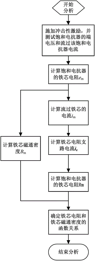
[0039] Such as figure 1 As shown, a method for modeling a converter valve saturated reactor core loss circuit model is provided, and the method includes the following steps:

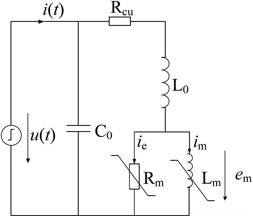
[0040] Step 1: Apply impulse excitation at both ends of the saturable reactor, and test the terminal voltage u(t) of the saturable reactor and the current i(t) flowing through the saturable reactor;

[0041] Step 2: Calculate the core resistance R of the saturable reactor m ;

[0042] Step 3: Calculate the core flux density B m ;

[0043] Step 4: Determine the core resistance R m and core flux density B m functional relationship.

[0044] In the step 1, the impulse excitation includes step voltage source, lightning impulse and steep slope impulse.

[0045] Described step 2 comprises the following steps:

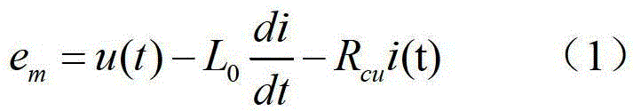
[0046] Step 2-1: Calculate the terminal voltage e of the core resistance ...


PUM


Abstract

The invention provides a modeling method for a converter valve saturable reactor iron core loss circuit model, which comprises the following steps: exerting impulse excitation at two ends of a saturable reactor; measuring the terminal voltage of the saturable reactor and the current passing the saturable reactor; obtaining the relationship between the resistance of the iron core and the magnetic flux density of the iron core through strict mathematical derivation and reasonable approximation hypothesis; and establishing the functional relationship between the resistance of the iron core and the magnetic flux density of the iron core through numerical fitting. According to the invention, the functional relationship between the resistance of the iron core and the magnetic flux density of the iron core is established through numerical fitting; as the nonlinear resistance is adopted to present the loss change process of the iron core, the actual physical process can be reflected accurately; and meanwhile, the linear function is adopted to present the resistance of the iron core, so that the fitting result is highly accurate as well, the physical conception is clear, and the modeling method is suitable for engineering application.

Description

technical field [0001] The invention belongs to the technical field of power electronics, and in particular relates to a modeling method for a circuit model of a core loss circuit model of a saturated reactor of a converter valve. Background technique [0002] In the turn-on transient state of the converter valve, the conduction of the thyristor starts near the gate, and the conduction area needs a certain period of time to gradually expand. If the current rises too fast, the resulting turn-on loss may cause device damage. In order to suppress the rate of change of current, a saturable reactor is required. There are stray capacitances in the converter transformer, and the capacitance and the inductance of the saturated reactor will oscillate in parallel. In extreme cases, the negative peak value of the oscillating current will be close to the positive peak value, so that the thyristor current will be turned off at zero just after it is turned on, causing damage to the device...

Claims


Application Information

Patent Timeline
Patent Type & Authority Applications(China)
IPC IPC(8): G06F17/50
Inventor 刘杰魏晓光曹均正纪锋
Owner GLOBAL ENERGY INTERCONNECTION RES INST CO LTD
Why Eureka
Try Eureka