
Combined transformer for power system

A technology combining transformers and power systems, applied in inductors, circuits, voltage dividers, etc., can solve problems such as voltage part must be calibrated on site, secondary signal processing loop is complex, and cannot be plug-and-play.

Active Publication Date: 2013-07-03
传奇电气(沈阳)有限公司
View PDF7 Cites 11 Cited by
  • Summary
  • Abstract
  • Description
  • Claims
  • Application Information

AI Technical Summary

Problems solved by technology

In addition, the processing circuit of the secondary signal is complicated, and the output signal is accompanied by white noise. When there is no primary current, due to the interference of white noise, the combined transformer will also output the secondary signal, which cannot meet the needs of billing.
If the voltage measurement adopts the technology of combining the capacitive voltage divider and the Pockels effect, the measurement error of the voltage part must also be calibrated on site, and it cannot be plug-and-play

Method used


Image

  • Combined transformer for power system
  • Combined transformer for power system
  • Combined transformer for power system

Examples


Embodiment Construction

[0055] In order to have a clearer understanding of the technical features, objectives and effects of the invention, the specific embodiments of the invention will now be described with reference to the drawings. The same reference numerals in each figure indicate the same or similar parts with the same function.

[0056] In order to make the drawings concise, the drawings only schematically show the parts related to the present invention, and they do not represent the actual structure of the product. In addition, in order to make the drawings concise and easy to understand, in some drawings, only one of the components with the same structure or function is schematically shown, or only one of them is marked.

[0057] In this article, "a" not only means "only this one", but can also mean "more than one". In this article, "parallel" between two objects does not mean absolute parallelism in the geometric sense, but can include the allowable deviation during assembly processing.

[0058]...


PUM


Abstract

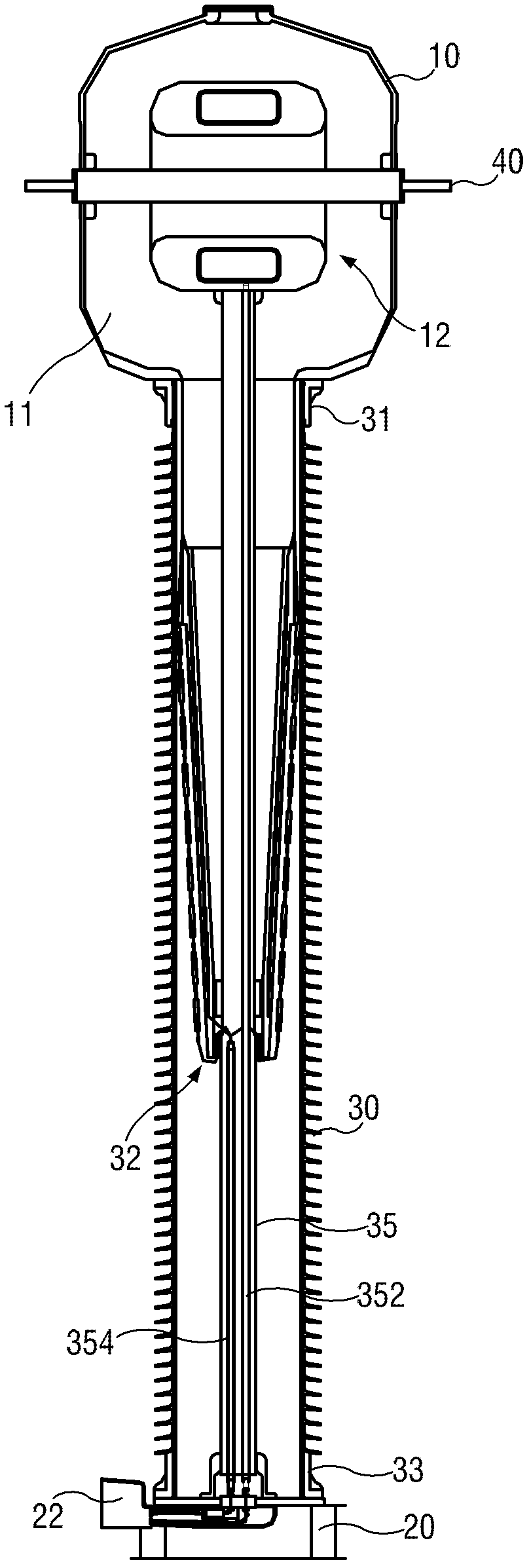
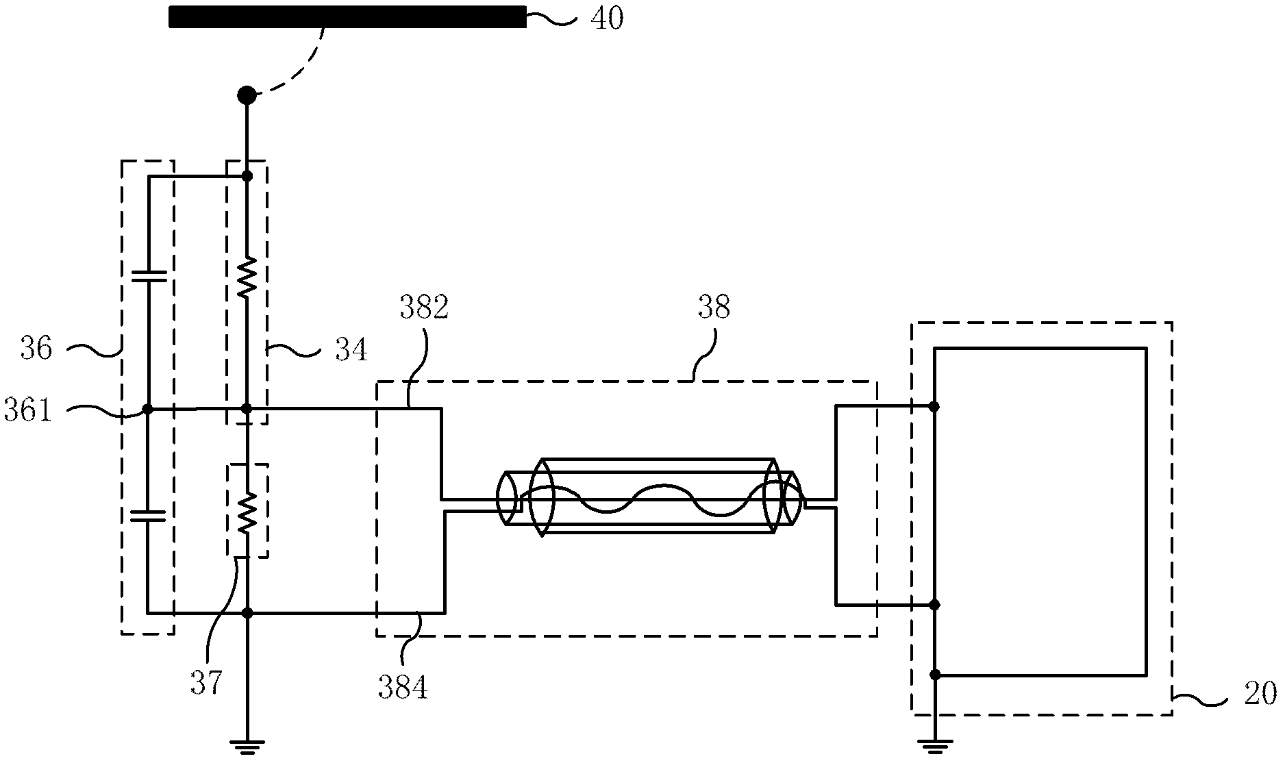
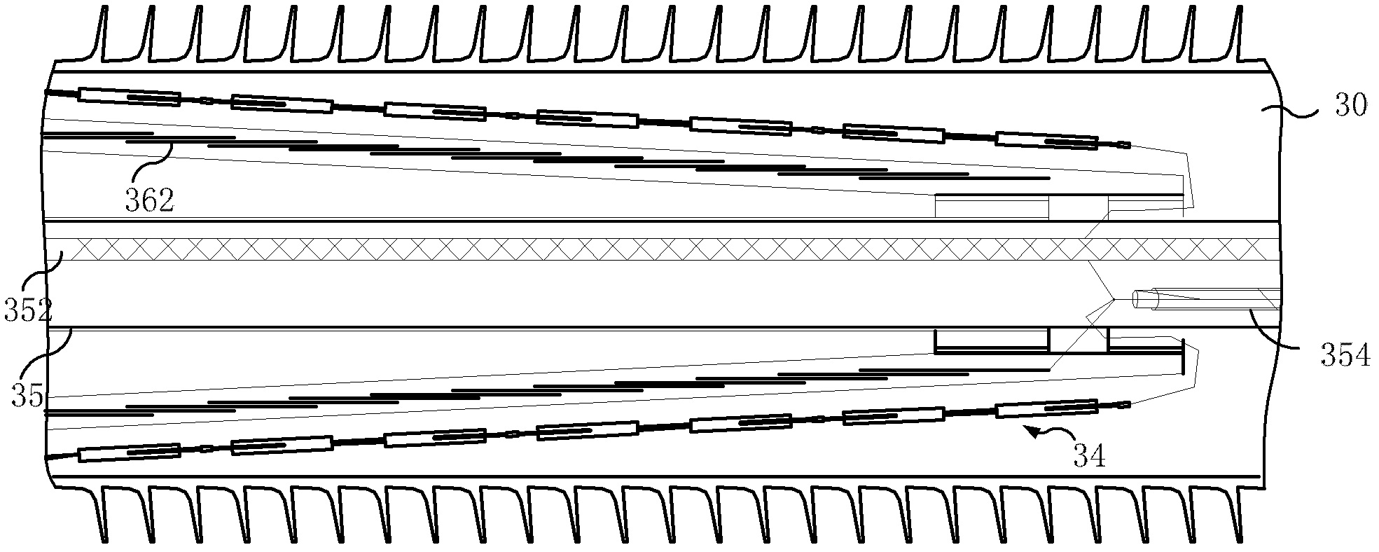
The invention provides a combined transformer for a power system. The combined transformer comprises a casing (10), a base (2) and an insulator (30). A current transformer (12) is arranged in the casing and can detect the current in a primary conductor (40) in the power system. A voltage transformer (32) is arranged in the insulator and comprises a resistance voltage division circuit (34), a capacitor voltage division circuit (36), a secondary voltage division resistor (37) and an output branch circuit (38), wherein one end of the resistance voltage division circuit is electrically connected with the primary conductor, and the other end is electrically connected with a secondary voltage division potential point of the capacitor voltage division circuit; and the capacitor voltage division circuit is realized by multiple layers of capacitive screens. The combined transformer for the power system, provided by the invention, can be used without error calibration after site installation, and can realize instant use after being plugged..

Description

Technical field [0001] The invention relates to a combined transformer used in a power system, in particular to an independent electronic combined transformer. Background technique [0002] The power system needs to use transformers to measure high voltage, high current and high voltage to realize the protection, control and electric energy measurement of the power system. In this process, the primary high voltage and the secondary low voltage need to be electrically isolated. The combined transformer is a device that has both current and voltage measurement functions and can simultaneously electrically isolate primary high voltage and secondary low voltage. [0003] In the traditional combined transformer, the current and voltage measurement adopt the electromagnetic transformer technology with iron core based on the principle of Faraday electromagnetic induction. At present, this combined transformer is widely used in power systems all over the world. Since the voltage transfo...

Claims


Application Information

Patent Timeline
IPC IPC(8): H01F38/34G01R15/06H01F38/36
Inventor 林芳敏
Owner 传奇电气(沈阳)有限公司
Learn More