Ultrasonic wave power source for driving magnetostrictive transducer

A magnetostrictive and transducer technology, which is applied in the direction of conversion equipment for intermediate conversion to DC conversion, etc., can solve the problems of hindering the application of magnetostrictive transducers, large size, and high power cost, and is conducive to miniaturization, The effect of simplifying the drive circuit and reducing the manufacturing cost

Inactive Publication Date: 2013-07-03
无锡正一生源科技有限公司
View PDF6 Cites 4 Cited by
  • Summary
  • Abstract
  • Description
  • Claims
  • Application Information

AI Technical Summary

Problems solved by technology

The disadvantage of this is also obvious. Due to the addition of a DC path, the cost of the power supply is high and the volume is large, which is the main reason hindering the application of the magnetostrictive transducer.

Method used


Image

  • Ultrasonic wave power source for driving magnetostrictive transducer
  • Ultrasonic wave power source for driving magnetostrictive transducer
  • Ultrasonic wave power source for driving magnetostrictive transducer

Examples


Embodiment Construction

[0016] The present invention will be further described below in conjunction with specific drawings and embodiments.

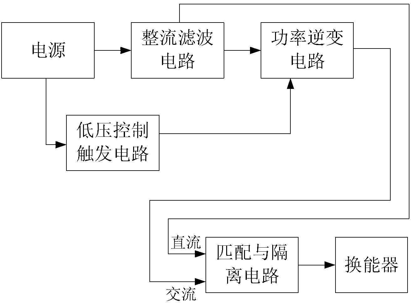
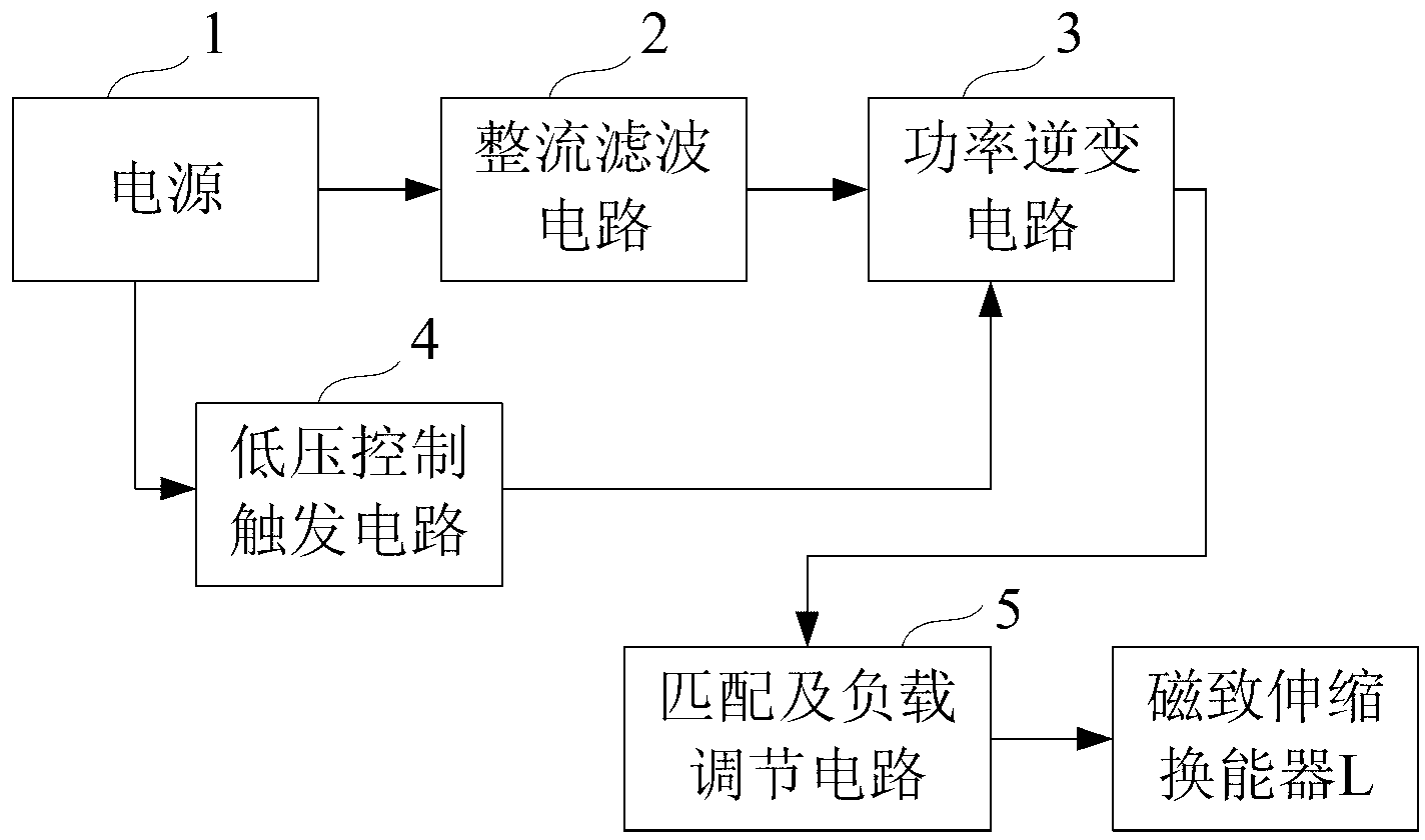
[0017] The circuit block diagram of the present invention is as figure 2 As shown, it includes a rectification filter circuit 2, a power inverter circuit 3, a low-voltage control trigger circuit 4 that outputs a control signal to the power switch tube in the power inverter circuit 3, a matching and load regulation circuit 5; the input terminal of the rectification filter circuit 2 Connect the power supply 1, the output terminal is connected to the power inverter circuit 3; the low-voltage control trigger circuit 4 is respectively connected to the power supply 1 and the power inverter circuit 3; the power inverter circuit 3 is connected to the matching and load regulation circuit 5, and the matching and load regulation circuit 5 is connected to the magnetic Scaling transducer L. and figure 1 Compared with the schematic block diagram of the traditional ultraso...


PUM


Abstract

The invention provides an ultrasonic wave power source for driving a magnetostrictive transducer. The ultrasonic wave power source comprises a rectifying filtering circuit, a power inversion circuit, a low pressure control triggering circuit for outputting a control signal of a power switching tube in the power inversion circuit and a matching and load regulation circuit, wherein the matching and load regulation circuit comprises a high frequency output transformer T, and the primary side of the high frequency output transformer T is connected with the power inversion circuit. The improvement of the ultrasonic wave power source provided by the invention is as follows: the matching and load regulation circuit also comprises a diode D and a resistor R5, and the diode D and the resistor R5 are connected in parallel so as to be connected in series with the magnetostrictive transducer in an auxiliary side loop of the high frequency output transformer T; the ultrasonic wave power source provided by the invention can be used for realizing the purpose that an electric current flowing the magnetostrictive transducer is a plus-minus semi-revolution dissymmetry alternate current, a direct-current channel is not needed to be additionally increased, and the transducer can normally operate in a bias magnetic state; and the driving circuit of the magnetostrictive transducer is simplified.

Description

technical field [0001] The invention relates to an ultrasonic power supply, in particular to an ultrasonic generator for driving a magnetostrictive transducer. Background technique [0002] At present, power ultrasonic is widely used in cleaning, welding, extraction of active ingredients of plants, sonochemistry and other fields. Ultrasonic waves used in industry are usually converted by electromagnetic waves of a certain frequency through transducers. The ultrasonic transducer includes a power supply part and a transducer part, wherein the transducer includes a piezoelectric transducer and a magnetostrictive transducer. Piezoelectric transducers have high energy conversion efficiency and low cost, and occupy a dominant position in the market. However, even if its energy conversion efficiency is high, it is still unavoidable to generate heat due to the dielectric loss and mechanical loss of the transducing material during the working process of the transducer. An increase...

Claims


Application Information

Patent Timeline
Patent Type & Authority Applications(China)
IPC IPC(8): H02M5/44
Inventor 孙赟硕
Owner 无锡正一生源科技有限公司
Why Eureka
Try Eureka