
Leakage detection and leakage location in supply networks

A supply network, regional technology, applied in the field of leak identification and location, which can solve the problems of high cost and related personnel burden

Active Publication Date: 2013-07-03
SIEMENS AG
View PDF7 Cites 15 Cited by
  • Summary
  • Abstract
  • Description
  • Claims
  • Application Information

AI Technical Summary

Problems solved by technology

This is both expensive and a burden on those involved

Method used


Image

  • Leakage detection and leakage location in supply networks
  • Leakage detection and leakage location in supply networks
  • Leakage detection and leakage location in supply networks

Examples


Embodiment Construction

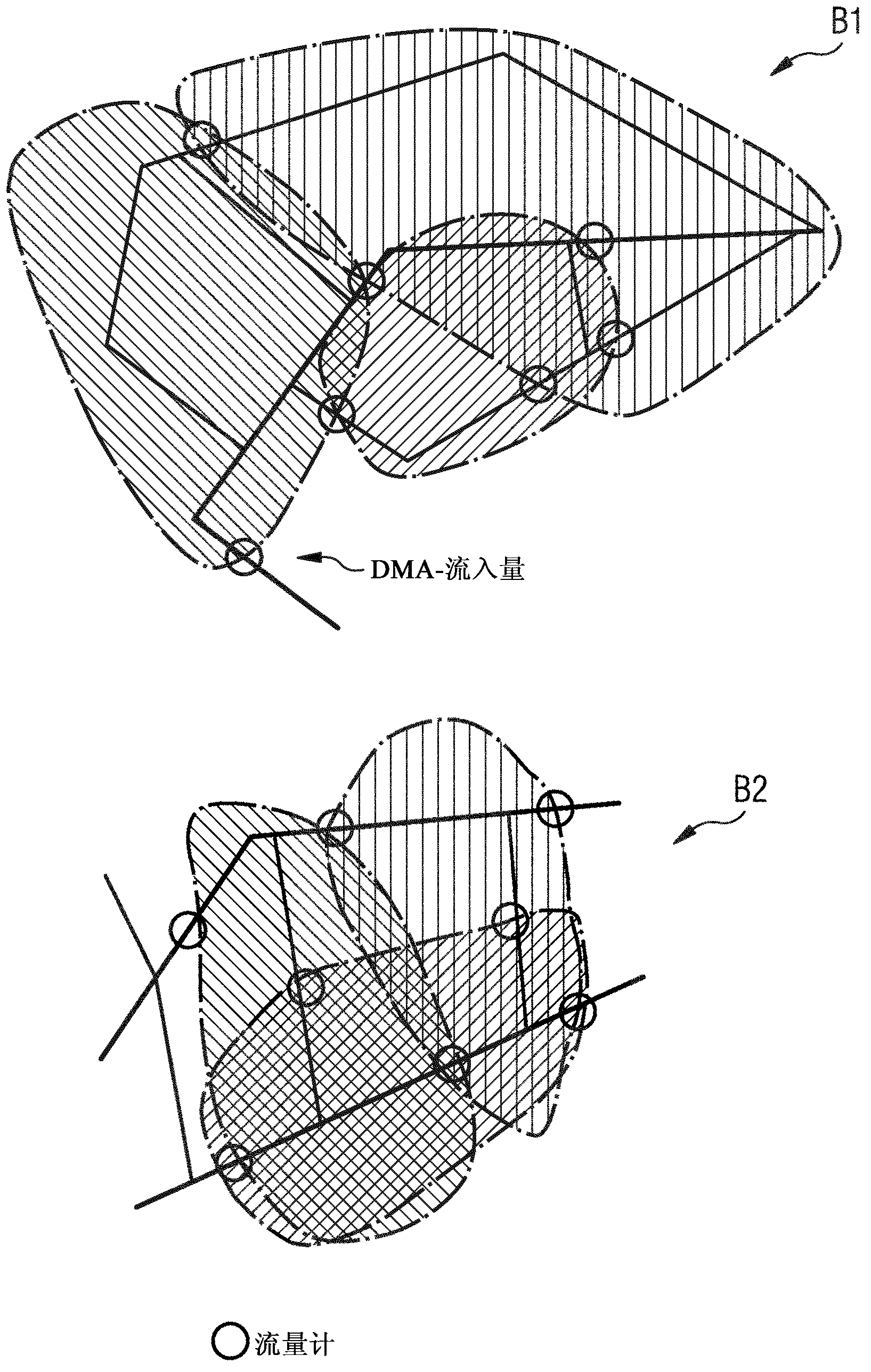
[0034] The reduction of water losses places great demands on the identification and location of leaks in water networks. Water losses can be identified in subregions of the network by flow measurement and formation of mass balances at all inflows and outflows of the region.

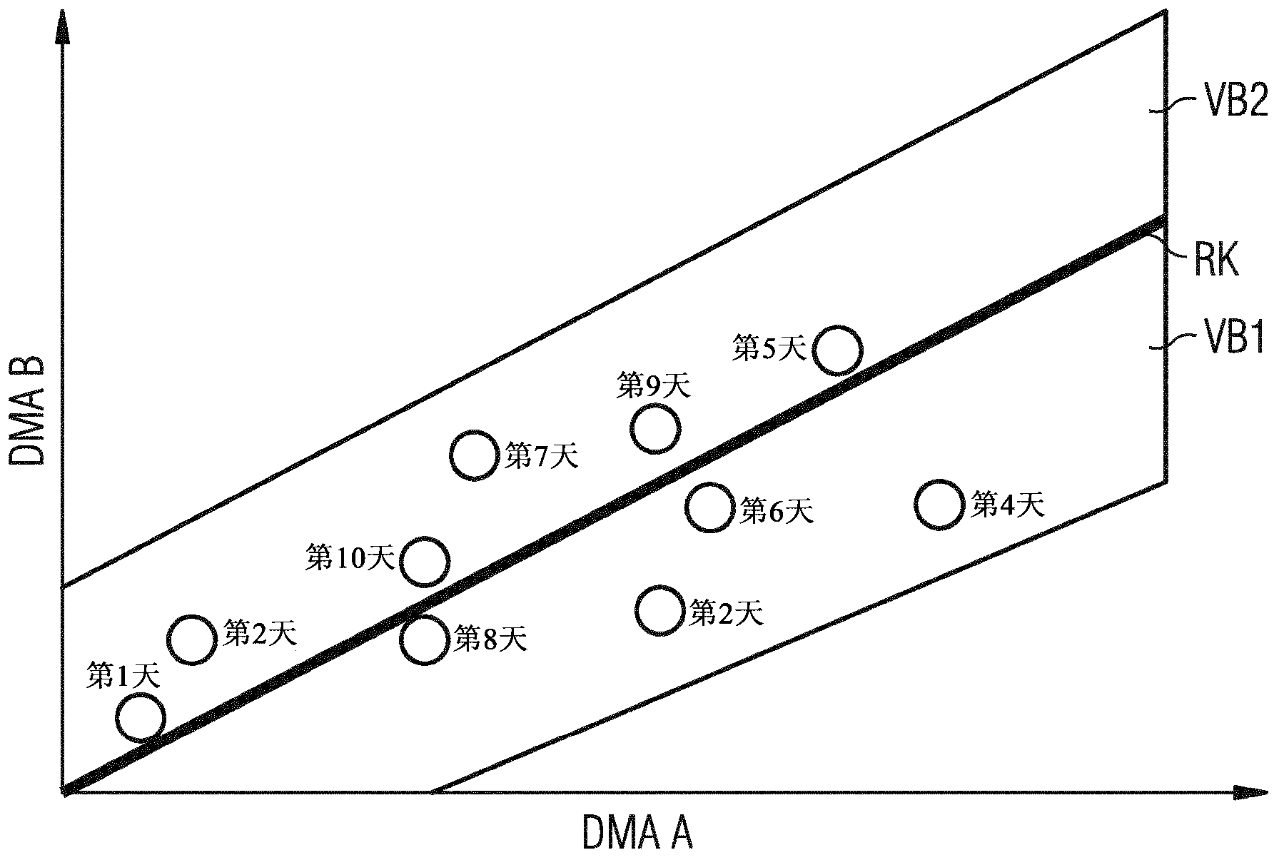
[0035] Such a measurement is not only feasible in terms of investment but also legally (time-accurate consumption measurement and recording of all users may cause problems in terms of data protection law) beyond the bounds of feasibility. Despite this, new and more advantageous measuring devices enable the monitoring of physically important values ​​such as pressure, flow, etc. Such measurements can be made at multiple locations in the water network. The values ​​obtained periodically in a given period of time are combined into a time series which is investigated using statistical methods for signs of existing or newly created leaks. If the statistical evaluation reports a leak, then the exact location ...


PUM


Abstract

The invention relates to a method and device for leakage detection and leakage location in an area of a supply network (e.g. water supply, gas supply or district heating network), wherein measurement values of sensors of the supply network are statistically analysed for the presence of leakages using robust regression methods. The false alarm rate (type 2 error) is in particular minimised.

Description

technical field [0001] The invention relates to a method, a use and a device for detecting and locating leaks in the region of a supply network. Background technique [0002] In the 21st century, drinking water is among the most important items during this period. However, there are sometimes significant water losses in the water distribution network. [0003] The custody of such items places great demands on leak identification and leak location in water networks. The method of identifying water loss by means of a mass balance, in which all injections and especially water losses of all individual water consumers are measured, exceeds feasible limits in terms of inputs. In addition, time-accurate consumption measurements and consumption logging of all user data are legally required. [0004] Leaks in water networks are traditionally detected only by measuring the overall water flow into the network at certain times, for example, during the time period between 2 and 4 o'cl...

Claims


Application Information

Patent Timeline
IPC IPC(8): G01M3/26G01M3/28F17D5/02
CPCG01M3/26G01M3/2807F17D5/02G01M3/00G06F17/10
Inventor 霍尔格·翰斯库尔特·马耶夫斯基约尔格·尼费勒扬·克里斯托弗·韦尔施泰特
Owner SIEMENS AG
Learn More