
Electric-control mechanical stepless row spacing regulator for seeder

A technology of planter and regulator, applied in the directions of planter parts, applications, fertilization devices, etc., can solve the problems of inability to adapt to the national conditions of small plot farming, inability to achieve plant spacing, stepless adjustment, etc., to eliminate the phenomenon of oscillation, structure Simple and efficient results

Inactive Publication Date: 2015-01-28
SHANDONG UNIV OF TECH
View PDF4 Cites 0 Cited by
  • Summary
  • Abstract
  • Description
  • Claims
  • Application Information

AI Technical Summary

Problems solved by technology

At present, the distance between plants of corn planters in the domestic market is mainly adjusted by changing gear meshes with different transmission ratios. Realize step-by-step adjustment of plant-to-plant distance, but cannot realize stepless adjustment of plant-to-plant distance
The variable-variable seeder produced in the United States uses an electronically controlled hydraulic motor variable fertilization and seeding actuator, and controls the speed of the hydraulic motor by changing the opening of the hydraulic proportional valve to achieve stepless adjustment. However, this type of adjustment mechanism is complex in design and high in cost, and cannot adapt to China. The National Conditions of Small Field Farming

Method used


Image

  • Electric-control mechanical stepless row spacing regulator for seeder
  • Electric-control mechanical stepless row spacing regulator for seeder
  • Electric-control mechanical stepless row spacing regulator for seeder

Examples


Embodiment Construction

[0032] exist Figure 1-8 In the example shown:

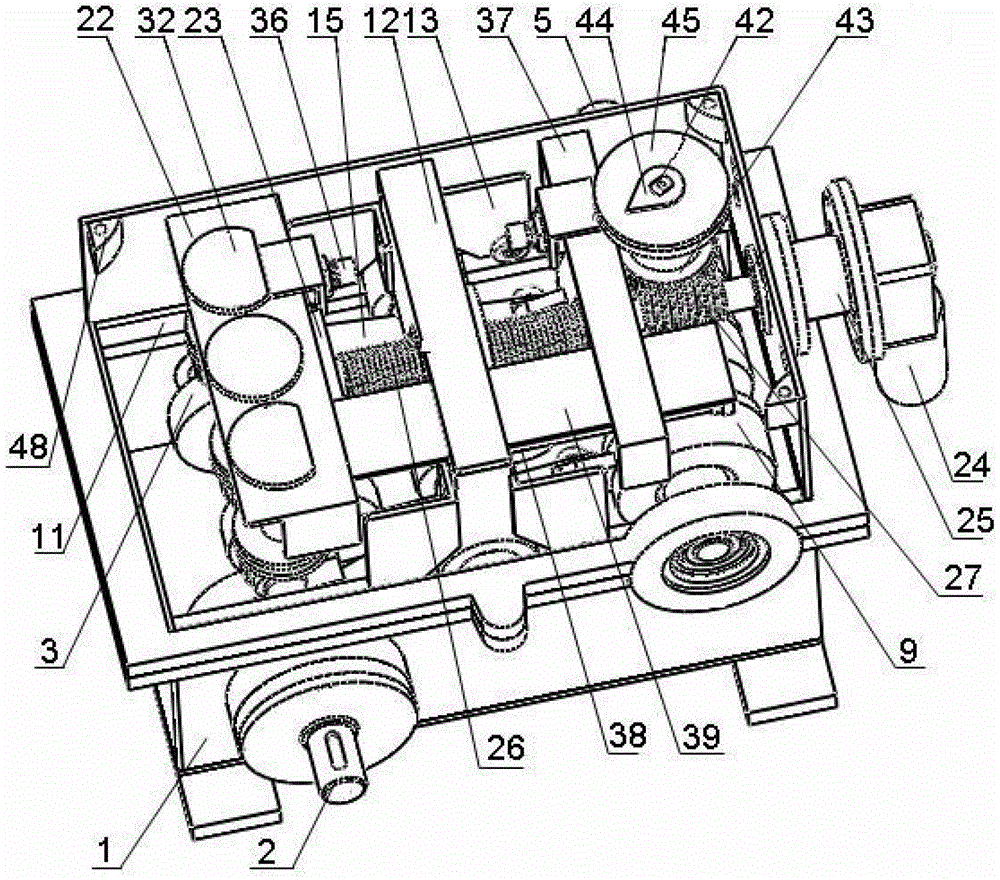
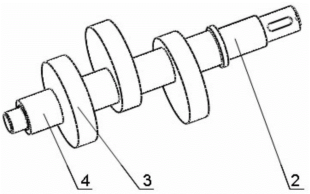
[0033] The power input device is installed in the lower part of the box body 1, including the input shaft 2 supported horizontally on the box body 1 via bearings, three cams 3 fixed on the input shaft 2 and the spacer sleeve I4 installed between the cams 3 at intervals , where three cams 3 are fixed on the input shaft 2 at 120°.

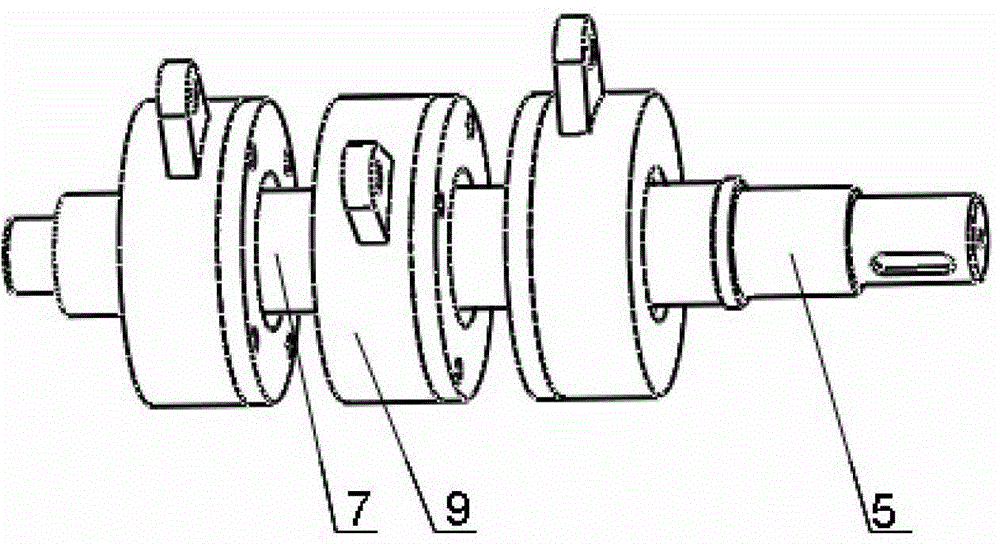
[0034] The power output device is installed on the upper part of the box body 1, including the output shaft 5 supported horizontally on the box body 1 via bearings, three overrunning clutches 6 and four spacer sleeves II7, of which the three overrunning clutches 6 are all fixed on the output shaft 5, the interval between adjacent overrunning clutches 6 is spacer II 7; corresponding to each overrunning clutch 6, a clutch end cover 8 and a clutch housing hub 9 are provided, and the overrunning clutch 6 is located between the clutch end cover 8 and the clutch housing hub 9 In the cavity formed by dockin...


PUM


Abstract

The invention relates to an electric-control mechanical stepless row spacing regulator for a seeder. The electric-control mechanical stepless row spacing regulator comprises a tank body, and a power input device, a power output device, a transmission device, a regulating device, a plurality of sets of oscillating bar reset devices, a limiting device, a displacement detection device and a row spacing indicating device which are arranged in the tank body. The row spacing regulator is characterized in that the power input device comprises an input shaft, a spacer sleeve I and a plurality of cams spaced at a certain angle, two guide racks are arranged in the middle of two ends of a regulating rack, the lower end of the regulating rack is provided with oscillating shafts equal to the cams, roller oscillating bars penetrate the oscillating shafts at intervals, one end with a roller of each roller oscillating bar is pressed on the corresponding cam by the corresponding oscillating rod reset device, the other end of each roller oscillating bar is hinged with a clutch housing, a screw worm of the regulating device horizontally penetrates the regulating rack, one end, close to the worm, of the regulating device extends out of the tank body to be connected with a gear motor shaft, and a micro sliding block displacement sensor probe of the displacement detection device is fixed on the regulating rack. The electric-control mechanical stepless row spacing regulator for the seeder can be used for performing stepless regulation on row spacing so as to achieve variable seeding.

Description

technical field [0001] The invention relates to an electrically controlled mechanical stepless regulator for planter spacing, belonging to the technical field of agricultural machinery. Background technique [0002] When corn is sown, the distance between plants is the main parameter that affects the light received by corn plants and the yield of corn. Therefore, the spacing adjustment is an important device for corn precision seeders. At present, the distance between plants of corn planters in the domestic market is mainly adjusted by changing gear meshes with different transmission ratios. Realize the stepless adjustment of the distance between the plants, but can not realize the stepless adjustment of the distance between the plants. The variable-variable seeder produced in the United States uses an electronically controlled hydraulic motor variable fertilization and seeding actuator, and controls the speed of the hydraulic motor by changing the opening of the hydraulic...

Claims


Application Information

Patent Timeline
Patent Type & Authority Patents(China)
IPC IPC(8): A01C7/20A01C19/00
Inventor 马明建杜瑞成杨自栋巩丙才
Owner SHANDONG UNIV OF TECH
Learn More