Clamping device

A clamping device and clamping technology, applied in the direction of chucks, manipulators, manufacturing tools, etc., can solve problems such as uneven force and inability to clamp wafers

Active Publication Date: 2013-07-10
SHENYANG SIASUN ROBOT & AUTOMATION
View PDF7 Cites 7 Cited by
  • Summary
  • Abstract
  • Description
  • Claims
  • Application Information

AI Technical Summary

Problems solved by technology

During the wafer assembly process, it is inevitable that the wafer will be clamped. Most of the wafer clamping is carried out by moving one of the claws radially. The problem with this method is that during the pre-alignment process The wafer is first placed on the support of the pre-alignment machine, and then the claws rise to accept the wafer and exceed the support, and then clamp the wafer. If the three-claw type is used and one of the claws is movable, the other The two claws are not movable, that is to say, the other two claws always maintain a state whether they clamp or loosen the wafer. In this way, when the claws rise, it is entirely possible to lift the wafer up, making it impossible to clamp the wafer s consequence
In addition, some use two claws or four claws to clamp the edge of the wafer symmetrically and move relative to each other, so that the edge of the wafer is only subjected to forces from two opposite directions, and the force is uneven.

Method used


Image

  • Clamping device
  • Clamping device
  • Clamping device

Examples


Embodiment Construction

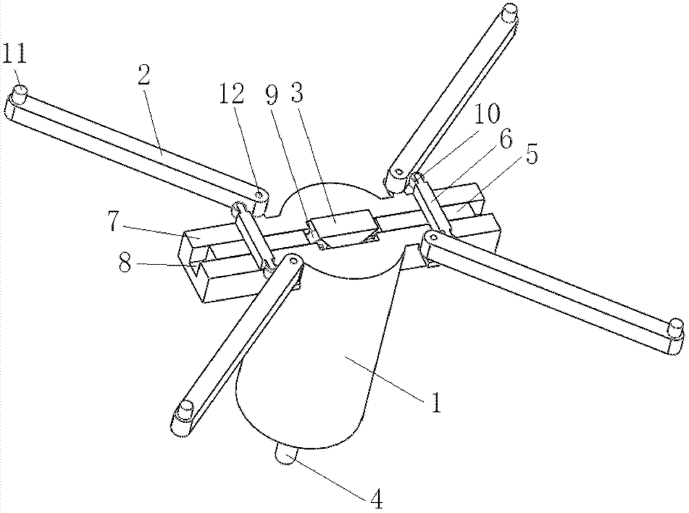
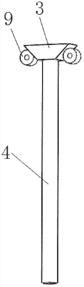
[0026] see figure 1 , in a preferred embodiment of the present invention, a clamping device includes a claw shaft 1, two sliding tables 7 arranged on the claw shaft, a contact between the two sliding tables 7 Unit 3, and the four claw arms 2 arranged on the two sliding tables 7. In one embodiment, the lengths of the four claw arms 2 are approximately equal.

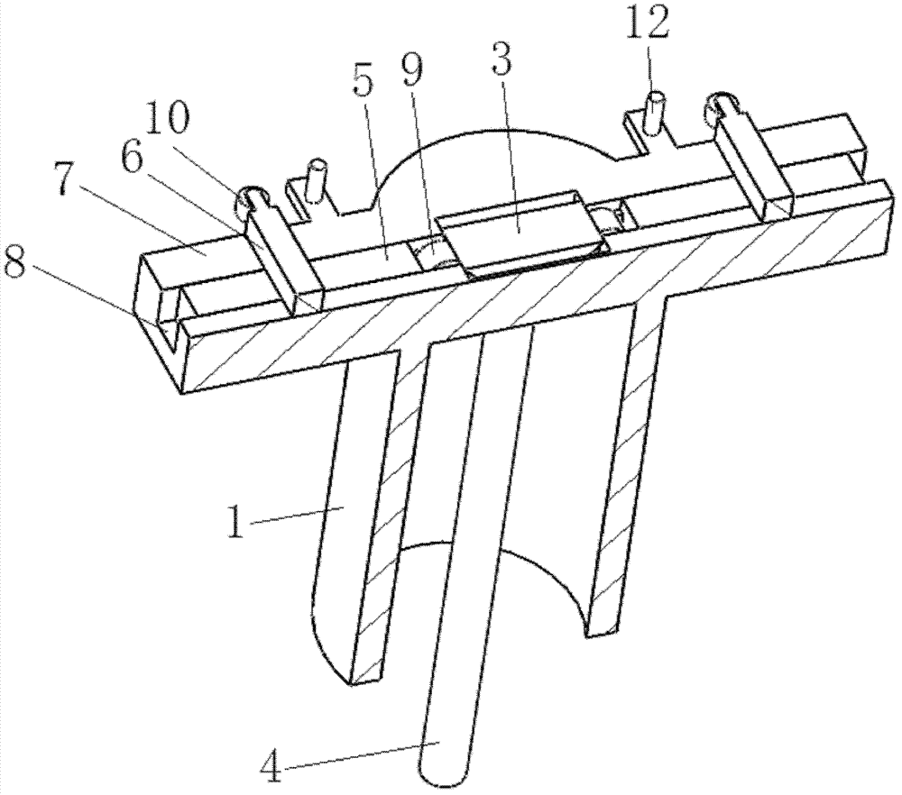
[0027] The claw shaft 1 is roughly shaped as a hollow cylinder with a centerline. One end of the jaw shaft 1 is provided with two sliding tables 7, and the other end is provided with an opening (not marked). In one embodiment, the two sliding platforms 7 are center-symmetric, and the center of symmetry is located on the center line of the jaw shaft 1 .

[0028] Please refer to figure 2 , the two slide tables 7 are provided with two chute 8 in the direction perpendicular to the centerline of the claw shaft 1, and a slide bar 5 is slidably housed in the chute 8. In one embodiment, both the sliding groove 8 and the sli...


PUM


Abstract

The invention discloses a clamping device which comprises a clamping shaft and two sliding tables which are arranged in symmetry relative to the central line of the clamping shaft, wherein the two sliding tables are respectively provided with sliding rods which can slide; the clamping device further comprises four clamping arms with the same lengths and a contacting unit; the four clamping arms are respectively rotationally fixed on two sides of the two sliding tables; the four clamping arms are respectively provided with clamping units; the four clamping units are arranged in symmetry relative to the central line of the clamping shaft; the two sliding rods are respectively connected with thrust rods; two opposite ends of each thrust rod are respectively and elastically connected with one clamping arm; the contact unit is clamped between the two sliding rods in a sliding manner; and the distance from the four clamping units to the central line of the clamping shaft can be changed simultaneously along the contact unit moves in the direction of the central line of the clamping shaft.

Description

technical field [0001] The invention relates to an auxiliary device for manufacturing, in particular to an auxiliary device for clamping manufacturing. Background technique [0002] With the development of science and technology, the scale of industrial production is getting bigger and bigger, so the labor cost will increase, and the efficiency requirements are getting higher and higher. Gradually, a large number of automation tools are introduced in the factory, such as the use of robots and other tools to assemble products. During the wafer assembly process, it is inevitable that the wafer will be clamped. Most of the wafer clamping is carried out by moving one of the claws radially. The problem with this method is that during the pre-alignment process The wafer is first placed on the support of the pre-alignment machine, and then the claws rise to accept the wafer and exceed the support, and then clamp the wafer. If the three-claw type is used and one of the claws is mova...

Claims


Application Information

Patent Timeline
Patent Type & Authority Applications(China)
IPC IPC(8): B25J15/10
Inventor 曲道奎王鲁非边弘晔徐方李学威何书龙冯亚磊张鹏
Owner SHENYANG SIASUN ROBOT & AUTOMATION
Why Eureka
Try Eureka