Two-stage bi-directional high-precision hydraulic synchronous control system

A hydraulic synchronization and control system technology, applied in the direction of fluid pressure actuators, servo motors, mechanical equipment, etc., can solve the problems of multi-cylinder high-precision synchronization difficulties, focus on high-precision synchronization, and no significant improvement, so as to avoid subversion Sexual consequences, improved reliability, fast response

Inactive Publication Date: 2013-07-10
CENT SOUTH UNIV
View PDF5 Cites 9 Cited by
  • Summary
  • Abstract
  • Description
  • Claims
  • Application Information

AI Technical Summary

Problems solved by technology

In the case of large load and large eccentric load, due to factors such as leakage, load change and strong interference, it is difficult to realize multi-cylinder high-precision synchronization
[0003] At present, in order to achieve multi-cylinder high-precision synchronous motion control, various advanced control theories are generally used in engineering to design control strategies and various controllers. Although these control methods can obtain high synchronization accuracy, they still have the following deficiencies: 1. The hydraulic principles of various hydraulic synchronous control systems in engineering are basically the same, and the key components are also proportional servo valves, which makes the performance of synchronous control mainly depend on the performance of hydraulic components, which has not been significantly improved for many years; 2. Emphasis Focus on the high-precision synchronization of the system while ignoring the high reliability of the system; 3. Only focus on the high-precision synchronization of one direction, and the research on the system that requires high-precision synchronization in both directions is still relatively blank

Method used


Image

  • Two-stage bi-directional high-precision hydraulic synchronous control system

Examples


Embodiment Construction

[0009] The present invention will be described in further detail below in conjunction with the accompanying drawings.

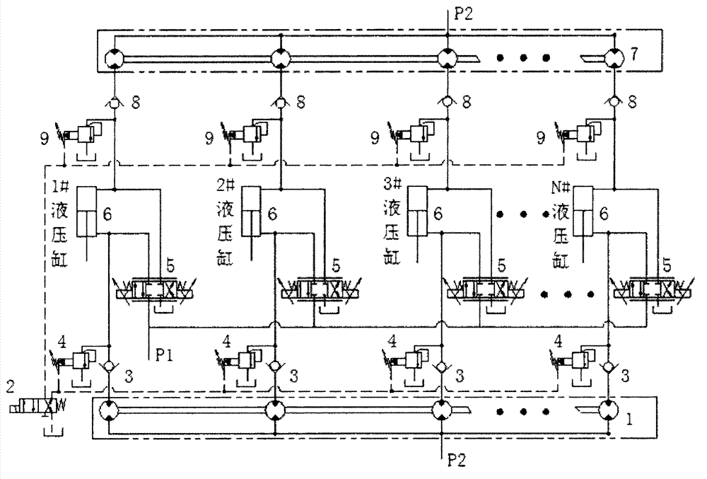
[0010] The two-stage two-way high-precision hydraulic synchronous control system of the present invention includes two sets of hydraulic synchronous motors, a two-position four-way electromagnetic reversing valve, 2N pilot relief valves, 2N one-way valves, and N proportional servo valves. N hydraulic cylinders, where N is the number of hydraulic cylinders. 2N pilot relief valves are divided into two groups, pilot relief valve 4 is a group, pilot relief valve 9 is a group; 2N check valves are divided into two groups, check valve 3 is a group, The one-way valve 8 is a group; the P port of the proportional servo valve 5 is connected to the oil source P1, the A and B ports are respectively connected to the rodless chamber and the rod chamber of the hydraulic cylinder 6, and the T port is connected to the oil tank; The oil inlet of the synchronous motor 1 is conn...


PUM


Abstract

The invention discloses a two-stage bi-directional high-precision hydraulic synchronous control system and relates to the field of multi-executing-mechanism synchronous control. The two-stage bi-directional high-precision hydraulic synchronous control system is mainly composed of a hydraulic synchronous motor, a proportional servo valve, a hydraulic cylinder, a check valve and pilot operated compound relief valves. The hydraulic synchronous motor is used for conducting a first stage of distribution on oil entering the hydraulic cylinder on a main oil line, then an oil port A and an oil port B of the proportional servo valve are connected with a rodless cavity and a rod cavity of the hydraulic cylinder respectively, and secondary adjusting is conducted on distributed flow of the hydraulic synchronous motor. In order to eliminate flow coupling between two groups of hydraulic synchronous motors, decoupling between inlet flow and outlet flow of the oil cylinder is achieved by connecting a remote control port of one group of pilot operated compound relief valve with an oil tank. Due to the fact that the hydraulic synchronous motor and the proportional servo valve are matched to adjust flow of a hydraulic cylinder oil inlet, a severe consequence caused by accidental damage or power down of the proportional servo valve is avoided, the reliability of the system is improved, and bi-directional high-precision synchronization of the system is guaranteed.

Description

technical field [0001] The invention relates to the technical field of high-precision synchronous control of multiple actuators, and is suitable for fields with high requirements for system reliability and bidirectional synchronous precision. Background technique [0002] Synchronous control has always been an important topic in the hydraulic industry, and its role is particularly prominent in the movement of heavy loads and large equipment. In the case of large load and large partial load, due to factors such as leakage, load change and strong interference, it is difficult to realize multi-cylinder high-precision synchronization. [0003] At present, in order to achieve multi-cylinder high-precision synchronous motion control, various advanced control theories are generally used in engineering to design control strategies and various controllers. Although these control methods can obtain high synchronization accuracy, they still have the following deficiencies: 1. The hydr...

Claims


Application Information

Patent Timeline
Patent Type & Authority Applications(China)
IPC IPC(8): F15B11/22
Inventor 胡军科杨文彬胡垠王子坡叶鑫
Owner CENT SOUTH UNIV
Why Eureka
Try Eureka