Connecting structure and mounting and fixing method for crankshaft and timing sprocket and engine
A timing sprocket and connecting structure technology, applied in the direction of engine components, machines/engines, valve devices, etc., can solve the problems of high assembly difficulty, inconvenient disassembly and maintenance, etc., to solve the problems of high assembly difficulty, convenient maintenance and disassembly, Easy to assemble effects
- Summary
- Abstract
- Description
- Claims
- Application Information
AI Technical Summary
Problems solved by technology
Method used
Image

Examples
Embodiment 1
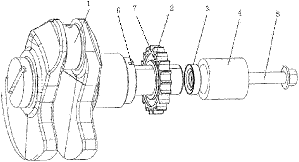
[0025] like figure 1 As shown, the present invention provides a connection structure of the crankshaft timing sprocket, the connection structure is arranged on the crankshaft 1 and the timing sprocket 2, and the connection structure includes: positioning groove 6, positioning key 7, sleeve 4 And the fixing bolt 5, the timing sprocket 2 and the sleeve 4 are sequentially sleeved on the crankshaft journal, the crankshaft 1 end surface is processed with the positioning groove 6, the timing sprocket 2 The positioning key 7 is processed on the surface matched with the crankshaft 1, the timing sprocket 2 forms a key connection with the crankshaft 1, the crankshaft 1 is provided with a threaded hole, and the fixing bolt 5 penetrates The threaded hole, and the sleeve 4 and the timing sprocket 2 are fixed on the crankshaft 1 through the fixing bolt 5 .
[0026] Refer to attached figure 1 As shown, the timing sprocket 2 is connected to the crankshaft 1 through the positioning groove 6 ...
Embodiment 2
[0034] see figure 1 , the present invention also provides a method for installing and fixing the crankshaft timing sprocket, which is applied to the connecting structure of the crankshaft 1 and the timing sprocket 2. The installation and fixing method is carried out according to the following steps: the timing chain Wheel 2, the oil seal 3 and the sleeve 4 are sleeved on the journal of the crankshaft 1, so that the positioning key 7 in the timing sprocket 2 is inserted into the positioning groove in the crankshaft 1 6, the timing sprocket 2 forms a key connection with the crankshaft 1, the fixing bolt 5 is inserted into the threaded hole, and the sleeve 4 and the timing The sprocket 2 is fixed on the crankshaft 1 , the sleeve 4 and the timing sprocket 2 are sealed by the oil seal 3 , and the fixing bolt 5 has the oil seal 3 .
[0035] The embodiment of the present invention includes all the content of embodiment 1, so this embodiment processes positioning groove 6 on the end ...
Embodiment 3
[0037] see figure 1 As shown, the present invention also provides a kind of engine, described engine comprises crankshaft 1 and timing sprocket 2, and the connecting structure of described crankshaft 1 and described timing sprocket 2 is arranged on described crankshaft 1 and described timing On the sprocket 2, the connection structure includes: a positioning groove 6, a positioning key 7, a sleeve 4 and a fixing bolt 5, and the timing sprocket 2 and the sleeve 4 are sequentially sleeved on the crankshaft 1 On the neck, the positioning groove 6 is processed on the end surface of the crankshaft 1, the positioning key 7 is processed on the matching surface of the timing sprocket 2 and the crankshaft 1, and the timing sprocket 2 and the The crankshaft 1 forms a key connection, the crankshaft 1 is provided with a threaded hole, the fixing bolt 5 penetrates into the threaded hole, and the sleeve 4 and the timing sprocket 2 are fixed by the fixing bolt 5 on the crankshaft 1.
[003...
PUM
 Abstract
Description
Claims
Application Information
 - R&D
- Intellectual Property
- Life Sciences
- Materials
- Tech Scout
- Unparalleled Data Quality
- Higher Quality Content
- 60% Fewer Hallucinations
Browse by: Latest US Patents, China's latest patents, Technical Efficacy Thesaurus, Application Domain, Technology Topic, Popular Technical Reports.
© 2025 PatSnap. All rights reserved.Legal|Privacy policy|Modern Slavery Act Transparency Statement|Sitemap|About US| Contact US: help@patsnap.com