Hydraulic buffer system for rotary dampers

A technology of rotary damper and hydraulic buffer, applied in the direction of shock absorber, shock absorber, liquid shock absorber, etc., can solve the problem of oil leakage of hydraulic components and pipeline joints, unbalanced force on hydraulic cylinders, and inability of vehicles to run, etc. problems, to achieve the effect of improving competitiveness, simple pressure control, and low manufacturing cost

Active Publication Date: 2015-05-20
JOINTECH (SUZHOU) VEHICLE SYST CO LTD
View PDF6 Cites 0 Cited by
  • Summary
  • Abstract
  • Description
  • Claims
  • Application Information

AI Technical Summary

Problems solved by technology

Although this kind of hydraulic buffer control system can form different damping according to the change of the included angle of the vehicle, the structure of this kind of system is relatively complicated. There will be oil leakage, which will not only affect the performance of the vehicle, but also cause the vehicle to fail to operate in severe cases.

Method used


Image

  • Hydraulic buffer system for rotary dampers
  • Hydraulic buffer system for rotary dampers
  • Hydraulic buffer system for rotary dampers

Examples


Embodiment Construction

[0028] The technical solutions of the embodiments of the present invention will be clearly and completely described below in conjunction with the accompanying drawings of the present invention.

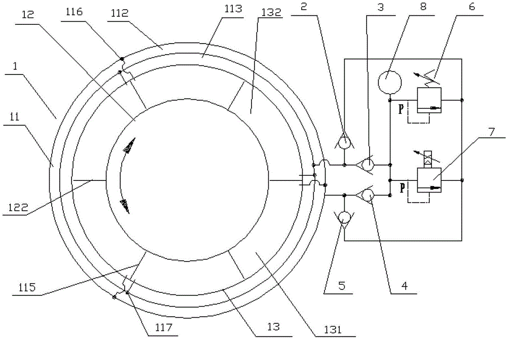
[0029] Such as figure 1 As shown, the rotary damper hydraulic buffer system disclosed in the present invention includes a rotary damper 1, a first one-way valve 2, a second one-way valve 3, a third one-way valve 4, a fourth one-way valve 5, an overflow A flow valve 6, a proportional relief valve 7 and a pressure sensor 8, the rotary damper 1 includes a stator 11, a rotor 12 rotating relative to the stator, and a hydraulic chamber 13 formed between the stator 11 and the rotor 12, the rotor 12 is located inside the stator 11, And concentrically arranged, the first oil passage 112 and the second oil passage 113 are arranged on the circumferential direction of the flange surface 111 of the upper end of the stator 11 . The hydraulic chamber 13 includes at least one first chamber 131 and a...


PUM


Abstract

Disclosed is a rotary damper type hydraulic buffer system, comprising a rotary damper, a first oil path and a second oil path, wherein the rotary damper comprises a stator, a rotor and a hydraulic chamber formed between the stator and the rotor; a first oil duct and a second oil duct are formed on the stator, and the hydraulic chamber comprises a first chamber and a second chamber which are respectively in communication with the first oil duct and the second oil duct; when the rotor rotates anticlockwise, a hydraulic oil in the first chamber is compressed, so as to enter the second chamber via the first oil duct, the first oil path and the second oil duct from the first chamber; and when the rotor rotates clockwise, the hydraulic oil in the second chamber is compressed, so as to enter the first chamber via the second oil duct, the second oil path and the first oil duct from the second chamber. The rotary damper type hydraulic buffer system of the present invention has a high level of integration and a good buffer effect; and two seals of an oil suction valve with an end surface and an axial plane ensure that the phenomenon of leakage will not occur.

Description

technical field [0001] The invention relates to the technical field of damping and shock absorbing control systems for vehicles, in particular to a hydraulic buffer system for a rotary damper. Background technique [0002] With the rapid development of my country's automobile manufacturing industry, various vehicle manufacturing industries are also advancing by leaps and bounds. Articulated buses are gradually popularized in large and medium-sized cities in China due to their large passenger capacity and high utilization coefficient. An articulated bus is generally composed of front and rear carriages and a chassis articulation system connecting the front and rear carriages. The chassis articulation system includes a front frame, a rear frame, a turntable bearing, and a hydraulic buffer device. The frame is fixedly connected with the rear compartment of the articulated vehicle through the rear beam. [0003] Among them, the hydraulic buffer device in the chassis articulated...

Claims


Application Information

Patent Timeline
Patent Type & Authority Patents(China)
IPC IPC(8): F16F9/14
CPCB60D5/00F16F9/145
Inventor 郝庆军
Owner JOINTECH (SUZHOU) VEHICLE SYST CO LTD
Why Eureka
Try Eureka