
Rack for equipment storage

A technology of equipment and skeleton, which is applied in the field of equipment storage racks, can solve the problems of strength, deformation, difficulty, etc., and achieve the effect of reducing the overall size

Active Publication Date: 2015-04-08
TAKIGEN MFG CO LTD
View PDF6 Cites 0 Cited by
  • Summary
  • Abstract
  • Description
  • Claims
  • Application Information

AI Technical Summary

Problems solved by technology

[0010] (1) In the case of a cabinet-type rack, since a plurality of devices are stored in one rack in multiple layers, when moving these devices inside or outside the house, it is difficult to connect the devices in the state where each device is stored in the rack. The rack is transported and set up together
In addition, even in the same installation place, when these devices are reassembled as a system into a layout that is easier to use, or when the layout of all or some devices is changed by changing or adding devices, it is necessary to take out and put each device into the rack. , and it is necessary to change the position of the platen according to each device, the operation becomes complicated and difficult
[0011] (2) In the case of a box-type rack, since the overall size is smaller than that of a cabinet-type rack, when moving these devices indoors or outdoors, it can be combined with various devices stored in the rack. This rack is transported and installed together, but in the case of this rack, since only the ends of a plurality of panels are connected to each other and welded or screwed, there is a strength problem. For example, when transporting this rack, when multiple When the racks are stacked on a vehicle, etc., the lower rack will be deformed by the weight of the upper rack, and the equipment inside the rack may be damaged.
In addition, when these racks for storing various equipment are piled up in a predetermined installation place according to the desired layout, similarly, the lower racks will be deformed by the weight of the upper racks, and the equipment inside the racks may be damaged. Various devices cannot be stacked together with racks in a free layout

Method used


Image

  • Rack for equipment storage
  • Rack for equipment storage
  • Rack for equipment storage

Examples


Embodiment Construction

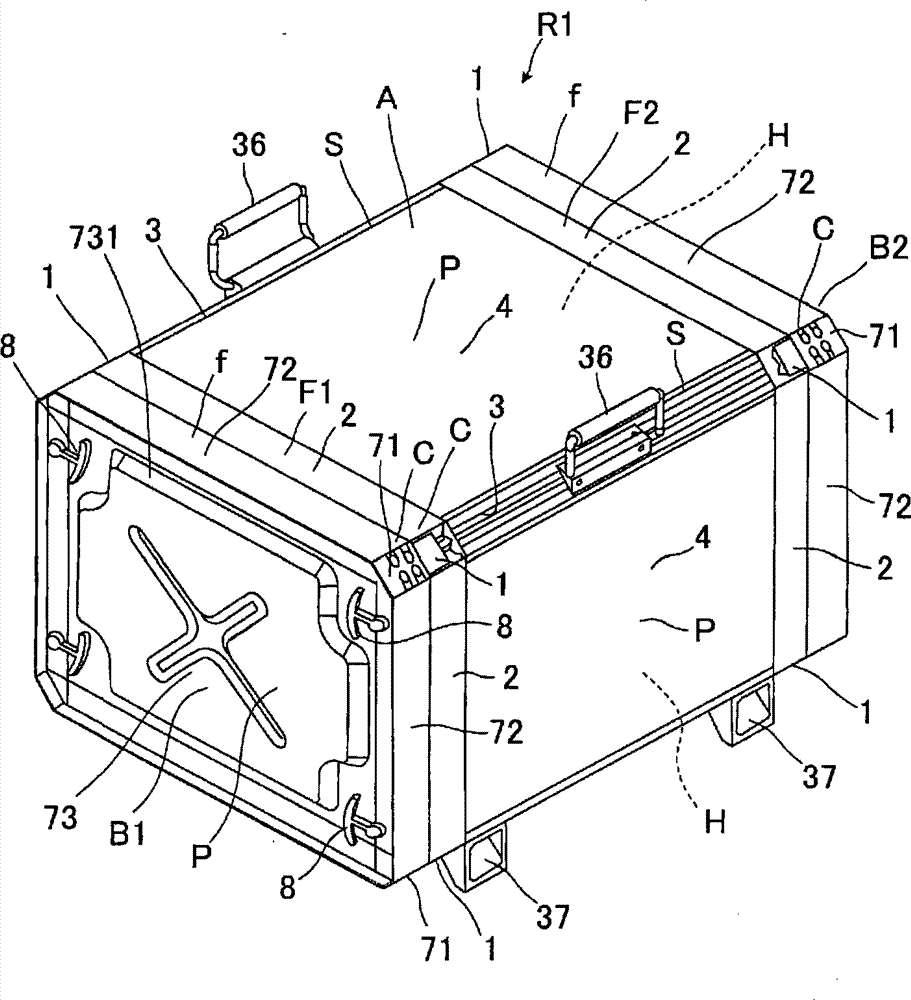
[0204] Next, an embodiment for carrying out the present invention will be described with reference to the drawings. exist figure 1 The structure of the equipment storage rack is shown in .

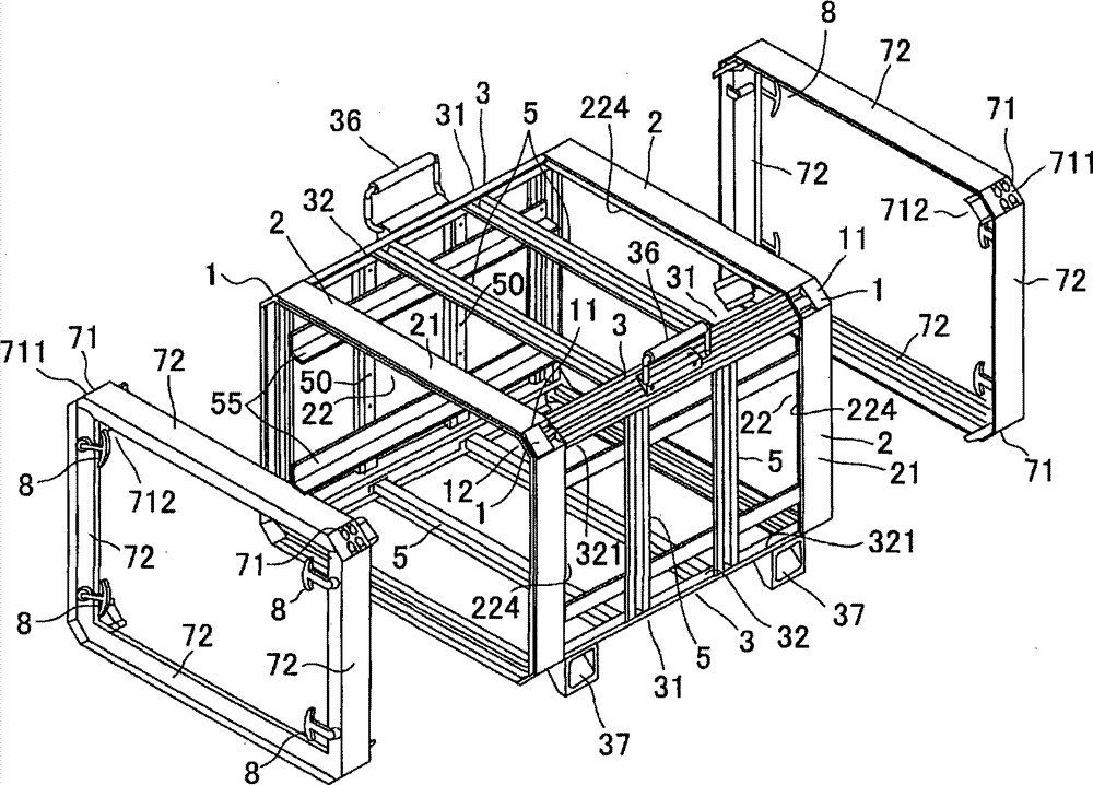
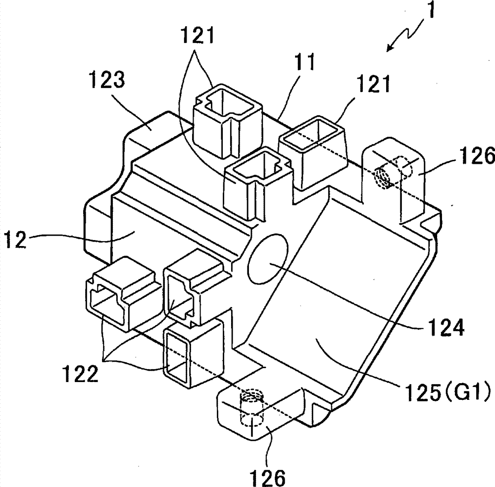
[0205] Such as figure 1 As shown, the equipment storage rack R1 has a front, a back, a top, a bottom, and left and right sides, and forms a box-shaped form as a whole, which is composed of a box-shaped rack body A and covers B1 and B2 on the front and back. As the constituent parts of the frame main body A, it includes: each corner C of the box shape and a corner block 1 made of aluminum material; each frame body F1, F2 constituting the front side and the back side of the box shape and made of aluminum material The formed frame constitutes the skeleton 2; forms the deep part S between the frame bodies F1 and F2 connected to the front side and the back side of the box shape and is made of aluminum material; Face P and the panel 4 that is made of aluminum material; Form the strengthening ...


PUM


Abstract

PURPOSE: A device storage rack is provided to easily change a layout by forming the rack with a block, a frame, and a panel of an aluminum material. CONSTITUTION: A corner block (I) forms each corner of a box shape and is formed by aluminum die casting. A border composition frame (2) is formed of an aluminum extrusion material and forms each border of the box shape by connecting a gap of the corner block. An inner length frame (3) is formed of the aluminum extrusion material and connects borders of the box shape. A panel (4) forms each surface of the box shape. A cover corner block (71) forms each cover corner of the box shape. A cover border composition frame (72) composes each cover border of the box shape. A cover panel (73) forms each surface of a box cover. A cover locking member (8) fixes the cover border composition frame and the border composition frame.

Description

technical field [0001] The present invention relates to an equipment storage rack used for storing various equipment such as computers, communication equipment, and electric equipment. In particular, it relates to equipment storage useful for storing, transporting, and installing various equipment, whether indoors or outdoors. Use rack. Background technique [0002] Generally, cabinet-type racks and box-type racks are known as such equipment storage racks. [0003] The cabinet frame is constructed as an overall long cabinet, in which the bottom plate and the top plate are connected by pillars, the panels are detachably installed on the left and right sides and the back, and a plurality of platens are arranged between the bottom plate and the top plate, and the front is free. A door is attached to open and close. In this manner, computers, communication equipment, electrical equipment, and the like are stored in multiple layers in the rack (for example, refer to Patent Docu...

Claims


Application Information

Patent Timeline
Patent Type & Authority Patents(China)
IPC IPC(8): F16M1/00
CPCA47B47/02H05K7/1487H05K7/1489
Inventor 濑川志朗
Owner TAKIGEN MFG CO LTD
Learn More