Storage battery parameter measurement device

A technology of parameter measurement and storage battery, which is applied in the status monitoring of storage battery and storage battery field, which can solve the problems of cumbersome measurement and scattered and complicated devices, and achieve the effects of reducing hidden dangers, improving safety and reducing measurement cost

Inactive Publication Date: 2013-07-10
上海大乘电气科技有限公司
7 Cites 7 Cited by

AI-Extracted Technical Summary

Problems solved by technology

[0006] In view of the above-mentioned shortcomings of the prior art, the object of the present invention is to provide a storage battery parameter measurement...

Method used

Visible in the present invention, what adopt is small pulse measurement, the millisecond level when the discharge current of accumulator, does not have any damage to accumulator, also improved the safety during device operation simultaneously, in addition, due to the discharge current of accumulator At the millisecond level, the resistance change of the standard resistor 132 due to heat is greatly reduced, thereby improving the accuracy of measuring the internal resistance of the storage battery.
[0060] It should be noted that since the present invention uses a small current with a period of milliseconds, the requirements for th...

Abstract

The invention provides a storage battery parameter measurement device which comprises a power supply module which is composed of storage batteries, an internal resistance measurement module, a voltage measurement module, a temperature measurement module and a display module. The internal resistance measurement module is used for measuring the internal resistance of each storage battery in the power supply module. The voltage measurement module is used for measuring the voltage of each storage battery in the power supply module. The temperature measurement module comprises storage battery temperature measurement chips which are arranged on the surfaces of the storage batteries. The power supply module supplies power for a single chip microcomputer which obtains the internal resistance, the voltage and the temperature of the storage battery according to a signal which is transmitted by the internal resistance measurement module, the voltage measurement module, and the temperature measurement module in sequence. The display module is used for displaying the internal resistance, the voltage and the temperature of each storage battery. The storage battery parameter measurement device possesses functions of measuring the voltage, the internal resistance and the temperature of the storage battery, is capable of measuring parameters such as voltages, resistances and temperatures of a plurality of storage batteries, and a storage battery maintainer can rapidly locate to the storage battery with bad performance parameters according to the voltage, the internal resistance and the temperature.

Application Domain

Technology Topic

Image

  • Storage battery parameter measurement device
  • Storage battery parameter measurement device

Examples

  • Experimental program(1)

Example Embodiment

[0046] The following describes the implementation of the present invention through specific specific examples. Those skilled in the art can easily understand other advantages and effects of the present invention from the content disclosed in this specification. The present invention can also be implemented or applied through other different specific embodiments, and various details in this specification can also be modified or changed based on different viewpoints and applications without departing from the spirit of the present invention.
[0047] It should be noted that the illustrations provided in this embodiment only illustrate the basic idea of ​​the present invention in a schematic way, and the figures only show the components related to the present invention instead of the number, shape, and shape of the components in actual implementation. For size drawing, the type, quantity, and proportion of each component can be changed at will during actual implementation, and the component layout type may also be more complicated.
[0048] Such as Figure 1 to Figure 2 As shown, the object of the present invention is to provide a battery parameter measuring device, which is used to solve the problems of large damage to the battery, high potential safety hazard, and complex and expensive measuring device when measuring the internal resistance of the battery in the prior art. The principle and implementation of the battery parameter measuring device of the present invention will be described in detail below, so that those skilled in the art can understand the battery parameter measuring device of the present invention without creative work.
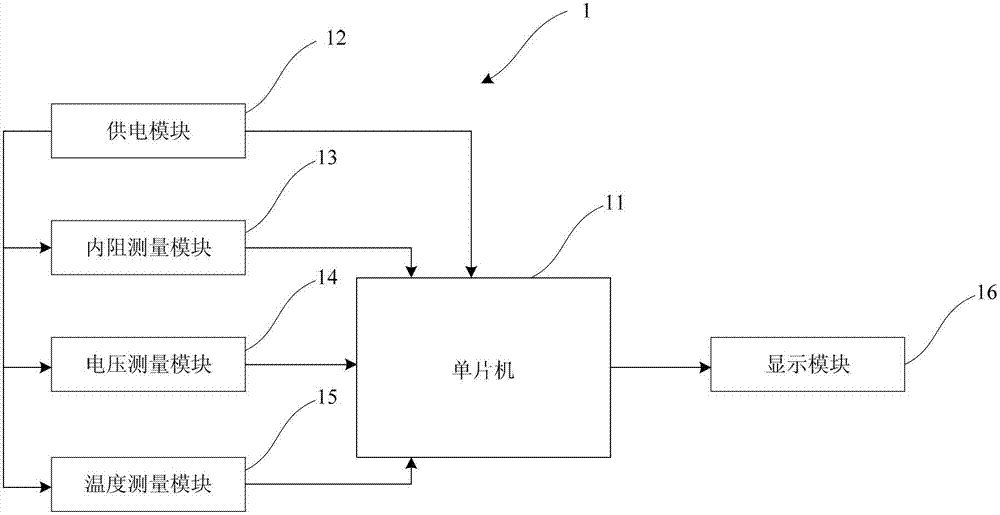
[0049] See figure 1 with figure 2 , Are respectively shown as a schematic diagram of the connection between a battery parameter measuring device and the remote control center and a schematic diagram of the structure of the battery parameter measuring device of the present invention. Such as figure 1 As shown, the present invention provides a battery parameter measurement device. The measurement device 1 includes a single-chip microcomputer 11, a power supply module 12, an internal resistance measurement module 13, a voltage measurement module 14, a temperature measurement module 15, and a display module 16.
[0050] The single chip microcomputer 11 includes an interface unit 111, and is connected to the power supply module 12, the internal resistance measurement module 13, the voltage measurement module 14, and the temperature measurement module 15 through the interface unit 111. The single chip computer 11 is powered by The module 12 supplies power, and the single-chip microcomputer 11 obtains the internal resistance, voltage, and temperature of the battery according to the signals sequentially transmitted from the internal resistance measurement module 13, the voltage measurement module 14, and the temperature measurement module 15. Therefore, in the present invention, the measurable battery parameters include the internal resistance, voltage and temperature of the battery. That is to say, the measuring device 1 of the present invention has three functions of measuring the internal resistance, voltage and temperature of the battery.
[0051] The power supply module 12 is composed of storage batteries, and there may be one or more storage batteries. For the convenience of description, in this embodiment, there are three storage batteries in the power supply module 12, such as figure 2 The battery 121, the battery 122, and the battery 123 shown in FIG. The storage battery supplies power for the operation of the single chip microcomputer 11 and its internal components. At the same time, in this embodiment, the storage battery is also used for measurement by the internal resistance measurement module 13, the voltage measurement module 14, and the temperature measurement module 15 while supplying power.
[0052] In addition, in this embodiment, in order to reduce the power consumption of the battery, the power supply module 12 independently supplies power to the single-chip 11 and the amplifying unit 113 in the single-chip 11. Since the amplifying unit 113 only works when the internal resistance of the battery is measured, When it is not in the measurement of the internal resistance of the battery, the power supply to the amplifying unit 113 is stopped, and the working power of the amplifying unit 113 is turned off to reduce power consumption.
[0053] The internal resistance measurement module 13 is connected to the power supply module 12 and is used to measure the internal resistance of each battery in the power supply module 12.
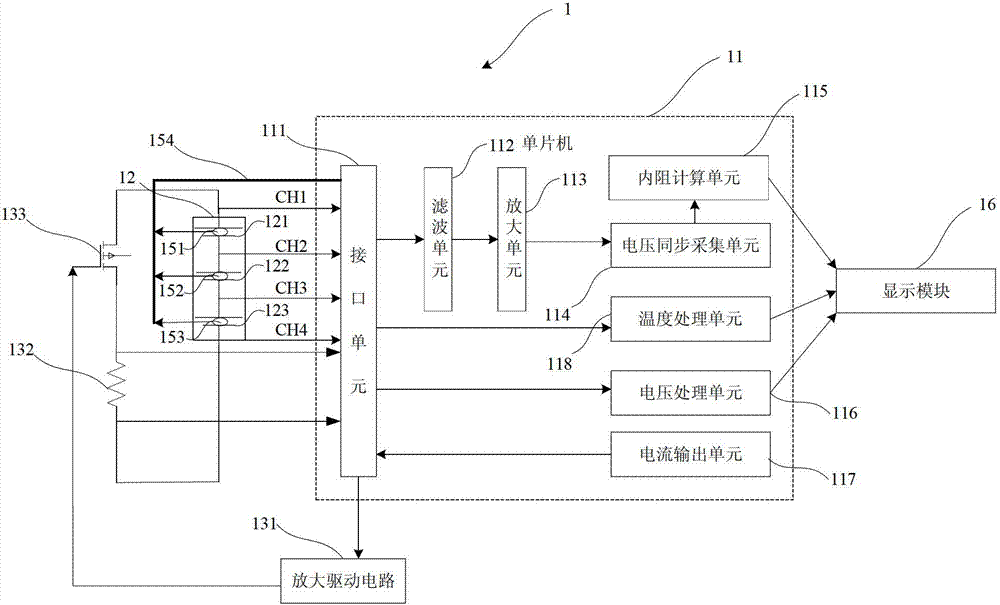
[0054] To measure the internal resistance of the battery, the single-chip microcomputer 11 includes: a current output unit 117, a voltage synchronous acquisition unit 114, and an internal resistance calculation unit 115; the internal resistance measurement module 13 includes: a standard resistor 132, a metal oxide half field effect transistor 133, Amplification driving circuit 131.
[0055] In this embodiment, the single-chip microcomputer 11 selects the single-chip microcomputer 11 that can output IDAC (current digital-to-analog converter). At least one pin (output port) of the single-chip microcomputer 11 can output a constant current, that is, the current output unit 117 can output Constant current, the current output unit 117 uses a timing method to intermittently output a certain constant current.
[0056] The magnitude of the constant current can be tens of milliamperes or hundreds of milliamperes, but not more than 1 ampere.
[0057] The standard resistor 132 is connected to the battery, and the standard resistor 132 is equivalent to forming a series circuit with the battery.
[0058] Here, when the standard resistor 132 is selected, the resistance value of the standard resistor 132 is already known. In fact, a standard resistor 132 with a specific resistance value is selected in series with the battery.
[0059] In this way, due to the series connection, when the battery is discharged, the current flowing through the standard resistor 132 and the battery is the same. If the voltage of the standard resistor 132 and the voltage of the battery are known, then according to Ohm’s law, that is, voltage, resistance and The relationship of the current can know the internal resistance of the battery.
[0060] It should be noted that, because the present invention uses a small current with a millisecond as a period, the standard resistance 132 is relatively low, which reduces the measurement cost.
[0061] The amplifying driving circuit 131 is connected between the current output unit 117 and the metal oxide half field effect transistor 133, and outputs a voltage square wave according to the constant current output by the current output unit 117 to drive the metal oxide half field effect Transistor 133.
[0062] After the constant current output by the current output unit 117 is amplified by the amplifying drive circuit 131, the amplifying drive circuit 131 outputs a voltage square wave with a stable amplitude. Because the constant current is output in an intermittent manner with a millisecond cycle, Therefore, the voltage square wave is also output from the amplifying driving circuit 131 in an intermittent manner with a millisecond period. In this embodiment, the current output unit 117 adopts a micro current generator built in a single-chip microcomputer.
[0063] Specifically, in this embodiment, the voltage output by the amplifying drive circuit 12 is used to drive the MOSFET 13 to turn on, and is generally a few volts.
[0064] Since the voltage period is in milliseconds, it is a small pulse. Since the small pulse measurement is adopted, the pulse time is less than the reaction time of equipment such as battery chargers, so the present invention can be used for online measurement, and the battery does not need to be measured offline, which greatly reduces various hidden dangers of the battery offline.
[0065] The MOSFET 133 is connected in the loop formed by the battery and the standard resistor 132 and is turned on and off intermittently according to the current output by the single chip computer 11.
[0066] The drain and source of the MOSFET 133 are respectively connected to the battery and the standard resistor 132, and the gate of the MOSFET 133 is connected to the amplifying drive circuit 131.
[0067] The voltage square wave from the amplifying drive circuit 131 is applied between the gate of the MOSFET 133 and the virtual ground. Since the voltage square wave is intermittent, a voltage is applied intermittently between the gate and the virtual ground, which will cause the MOSFET 133 to be turned on and off intermittently, namely The drain and source are turned on and off intermittently.
[0068] When the drain and source are connected, the battery discharges, and a square wave current flows through the standard resistor 132 and the battery at the same time. The voltage square wave produces a voltage drop V on the standard resistor 132 R =i×R, the voltage square wave produces a voltage drop V on the battery r =i×r, where R is the resistance value of the standard resistance 132. According to the previous description, the resistance value of this standard resistance 132 is known, r is the resistance value of the internal resistance of the battery, and i is the resistance value of the standard resistance 132 and The circuit of the battery, V r Is the voltage drop of the standard resistor 132, V R Is the voltage drop of the battery.
[0069] Specifically, the square wave current flowing between the drain and the source of the MOSFET 133 is also the discharge current of the battery. The square wave current flowing between the drain and source of the MOSFET 133 matches the magnitude of the constant current, and can be tens of milliamperes or hundreds of milliamperes, but not more than 1 ampere.
[0070] It can be seen that in the present invention, the small pulse measurement is adopted. The discharge current of the battery is in the order of milliseconds, which does not cause any damage to the battery. At the same time, it also improves the safety of the device during operation. In addition, because the discharge current of the battery is in the order of milliseconds , The resistance change of the standard resistor 132 due to heat is greatly reduced, thereby improving the accuracy of measuring the internal resistance of the battery.
[0071] The single-chip microcomputer 11 also includes a filtering unit 112 and an amplifying unit 113 that sequentially filter and amplify the collected and the battery voltage.
[0072] The voltage synchronization collecting unit 114 is used to collect the voltage of the battery. Specifically, the voltage synchronization acquisition unit 114 uses the A/D acquisition circuit of the single-chip microcomputer to acquire the voltage.
[0073] In the present invention, the power synchronization collecting unit only collects the voltage of one battery at a time, and the interface unit 111 of the single-chip 11 measures the voltage of each battery by switching different interfaces. Specifically, such as figure 2 As shown (take three batteries as an example), both ends of the battery 121 are connected to the wires CH1 and CH2 from the interface module, and both ends of the battery 122 are connected to the wires CH2 and CH3 from the interface module (the battery 121 and the battery 122 Sharing a wire CH2), the two ends of the battery 123 are connected to the wires CH3 and CH4 from the interface module (the battery 122 and the battery 123 share a wire CH3), the interface unit 111 of the single chip computer 11 switches the wires CH1, the wires CH2, and Wire CH3 and wire CH4 are connected to the corresponding port, which controls the collection of battery voltage between which two wires.
[0074] It can be seen that the voltage across the battery 121 is the voltage between the wire CH1 and the wire CH2, and the voltage across the battery 122 is the voltage between the wire CH2 and the wire CH3 (that is, the voltage between the wire CH1 and the wire CH3 Minus the voltage between the wire CH1 and the wire CH2), the voltage across the battery 123 is the voltage between the wire CH3 and the wire CH4 (that is, the voltage between the wire CH1 and the wire CH4 minus the voltage between the wire CH1 and the wire CH3 Voltage).
[0075] The internal resistance calculation unit 115 is used to calculate the internal resistance of the known standard resistance 132, the collected battery voltage, the voltage of the standard resistance 132, the internal resistance of the battery, the voltage of the battery, and the standard resistance 132 The internal resistance of the battery is calculated from the proportional relationship between the internal resistance and the voltage.
[0076] The voltage square wave produces a voltage drop V on the standard resistor 132 R =i×R, the voltage square wave produces a voltage drop V on the battery r =i×r, where R is the resistance value of the standard resistance 132. According to the previous description, the resistance value of this standard resistance 132 is known, r is the resistance value of the internal resistance of the battery, and i is the resistance value of the standard resistance 132 and The circuit of the battery, V r Is the voltage drop of the standard resistor 132, V R Is the voltage drop of the battery, V R The voltage synchronization acquisition unit 114 can obtain that V r It is directly input into the internal resistance calculation unit 115 through the interface of the single-chip microcomputer.
[0077] Since the standard resistance 132 is the same as the current i flowing in the battery, which is and so That is, the internal resistance of the battery can be based on the formula Calculated.
[0078] Specifically, the internal resistance calculation unit 115 according to the formula Calculate the resistance of the internal resistance of the battery, where r is the resistance of the internal resistance of the battery, R is the resistance of the standard resistor 132, and V r Is the voltage drop of the standard resistor 132, V R Is the voltage drop of the battery.
[0079] In order to enable those skilled in the art to further understand the principle of measuring the internal resistance of the battery in the present invention, the following describes the working process of the present invention for measuring the internal resistance of the battery.
[0080] The current output unit 117 in the single chip microcomputer 11 uses a timing method to output a constant current intermittently, and the amplifying drive circuit 131 outputs a square wave voltage with a constant amplitude according to the constant current, and the square wave voltage is applied to the metal oxide half field effect transistor 133 Between the grid and the virtual ground, the drain and source are intermittently turned on and off. When the drain and source are turned on, the battery is discharged, and a square wave current flows through the standard resistor 132 and The voltage synchronization acquisition unit 114 separately collects the voltage of the battery and the voltage of the standard resistor 132. The internal resistance calculation unit 115 is based on the formula Calculate the resistance value of the internal resistance of the battery, thereby obtaining the resistance value of the internal resistance of the battery.
[0081] The voltage measurement module 14 is connected to the power supply module 12 and is used to measure the voltage of each battery in the power supply module 12. The interface unit 111 of the single chip microcomputer 11 measures the voltage of each battery by switching different interfaces; the single chip 11 also includes a voltage processing unit 116 connected to the interface unit 111, and the voltage processing unit 116 processes the voltage from the interface Each voltage signal received by the unit 111 obtains the voltage of each battery. The voltage processing unit 116 can be implemented by an A/D processing circuit inside the single-chip microcomputer.
[0082] When the voltage measurement module 14 is working, the process of collecting the battery voltage is the same as when measuring the internal resistance of the battery. That is, the two ends of the battery 121 are connected to the wires CH1 and CH2 from the interface module, and the two ends of the battery 122 are connected to the wires CH2 and CH3 from the interface module (the battery 121 and the battery 122 share the same wire CH2). The terminal is connected to the wire CH3 and the wire CH4 from the interface module (the battery 122 and the battery 123 share a wire CH3), and the interface unit 111 of the single-chip microcomputer 11 switches the corresponding ports of the wire CH1, the wire CH2, the wire CH3, and the wire CH4. , Control the battery voltage between which two wires are collected.
[0083] It can be seen that the voltage across the battery 121 is the voltage between the wire CH1 and the wire CH2, and the voltage across the battery 122 is the voltage between the wire CH2 and the wire CH3 (that is, the voltage between the wire CH1 and the wire CH3 Minus the voltage between the wire CH1 and the wire CH2), the voltage across the battery 123 is the voltage between the wire CH3 and the wire CH4 (that is, the voltage between the wire CH1 and the wire CH4 minus the voltage between the wire CH1 and the wire CH3 Voltage).
[0084] However, in the present invention, the voltage measurement module 14 and the resistance measurement module cannot perform measurements at the same time. At the same time, only one of the internal resistance and voltage of the battery can be measured. Because in the resistance measurement module, the collected voltage signal and the voltage signal of the standard resistor 132 need to be analyzed and processed, at this time, the collected voltage signal directly enters the voltage synchronization collecting unit 114 in the single-chip 11. When the voltage measurement module 14 is working, the collected voltage signal directly enters the voltage processing unit 116 in the single-chip microcomputer 11.
[0085] The temperature measurement module 15 is connected to the power supply module 12 and includes a battery temperature measurement chip arranged on the surface of each battery; specifically, a battery temperature measurement chip 151 is attached to the surface of the battery 121, and a battery temperature measurement chip is attached to the surface of the battery 122 152. A battery temperature measuring chip 153 is attached to the surface of the battery 123. Each battery temperature measurement chip in the temperature measurement module 15 is connected to the single-chip computer 11 through a temperature measurement bus 154, that is, the battery temperature measurement chip 151, the battery temperature measurement chip 152, and the battery temperature measurement chip 153 are all connected to the temperature measurement bus On 154, the temperature measurement bus 154 is connected to the single chip microcomputer 11. Therefore, in the present invention, the temperature measurement module 15 can measure specific temperatures of multiple batteries.
[0086] The single-chip microcomputer 11 also includes a temperature processing unit 118 connected to the interface unit 111, and the temperature processing unit 118 is configured to obtain the temperature of each battery according to the signal transmitted from each battery temperature measurement chip. The temperature processing unit 118 can be implemented by an A/D processing circuit inside the single-chip microcomputer.
[0087] The temperature processing unit 118 can set the upper and lower limits of the temperature, and send an alarm signal when the temperature exceeds the upper and lower limits.
[0088] In this embodiment, the signal sent by each of the temperature measurement chips to the single-chip microcomputer 11 includes the temperature of the battery and the number used to identify the battery.
[0089] In addition, the single-chip microcomputer 11 is also connected with an environmental temperature measurement chip for measuring the environmental temperature.
[0090] The display module 16 is connected to the single-chip computer 11 and is used to display the internal resistance, voltage and temperature of each battery. Since the display module 16 can display the voltage, internal resistance, temperature and other parameters of multiple batteries at the same time, the battery maintenance personnel can quickly locate the batteries with poor performance parameters.
[0091] In summary, the battery parameter measuring device of the present invention has the following beneficial effects:
[0092] 1. The measurement device of the present invention connects the internal resistance measurement module, voltage measurement module, and temperature measurement module 15 to the same single-chip microcomputer, so that the measurement device of the present invention has the function of measuring battery voltage, internal resistance, and temperature.
[0093] 2. Because the device of the present invention integrates the measurement of voltage, internal resistance, and temperature, the measurement cost is significantly reduced.
[0094] 3. The device of the present invention is equipped with a display module, which can simultaneously display the voltage, internal resistance, temperature and other parameters of multiple batteries; battery maintenance personnel can quickly locate batteries with poor performance parameters.
[0095] 4. In the measurement of the internal resistance of the battery by the device of the present invention, various hidden dangers of the battery offline are greatly reduced, the battery is not damaged, and the safety of the device during operation is also improved.
[0096] 5. The device of the present invention has a simple structure and does not require signal generators, peak sampling devices and other devices.
[0097] Therefore, the present invention effectively overcomes various shortcomings in the prior art and has high industrial value.
[0098] The above-mentioned embodiments only exemplarily illustrate the principles and effects of the present invention, but are not used to limit the present invention. Anyone familiar with this technology can modify or change the above-mentioned embodiments without departing from the spirit and scope of the present invention. Therefore, all equivalent modifications or changes made by those with ordinary knowledge in the technical field without departing from the spirit and technical ideas disclosed in the present invention should still be covered by the claims of the present invention.

PUM

no PUM

Description & Claims & Application Information

We can also present the details of the Description, Claims and Application information to help users get a comprehensive understanding of the technical details of the patent, such as background art, summary of invention, brief description of drawings, description of embodiments, and other original content. On the other hand, users can also determine the specific scope of protection of the technology through the list of claims; as well as understand the changes in the life cycle of the technology with the presentation of the patent timeline. Login to view more.

Similar technology patents

Classification and recommendation of technical efficacy words

  • Reduce cost of measurement
  • Reduce hidden dangers

System for monitoring atmospheric particulates by utilizing social vehicles

InactiveCN107219157AReduce cost of measurementReduce one-time input costsTransmission systemsMobile data collection deviceTruckMeasurement cost
Owner:NOVA FITNESS CO LTD

Safety production management and control device, system and method

ActiveCN107885170ARealize closed-loop controlReduce hidden dangersTechnology managementTotal factory controlControl measureProduction control
Owner:ZHUHAI UNITECH POWER TECH CO LTD

Method and device for detecting memory

ActiveCN101599046AReduce hidden dangersConvenient program debuggingSoftware testing/debuggingBad memoryComputer program
Owner:SHENZHEN IPANEL TECH LTD

Helicopter rotor airfoil

InactiveCN106043688AReduce hidden dangersRotocraftTrailing edgeAerodynamics
Owner:NANJING UNIV OF AERONAUTICS & ASTRONAUTICS
Why Eureka
Try Eureka