Eureka AIR delivers breakthrough ideas for toughest innovation challenges, trusted by R&D personnel around the world.

Objective lens frame fixing device

A technology for fixing devices and frames, which is applied in installation, exposure devices for photolithography, and optics. It can solve the problems of lens stress affecting the quality of lithography machines, failing to meet fixed requirements, and low work efficiency. It achieves simple structure and easy installation. , The effect of high installation efficiency

Active Publication Date: 2013-07-10
SHANGHAI MICRO ELECTRONICS EQUIP (GRP) CO LTD
View PDF4 Cites 5 Cited by
  • Summary
  • Abstract
  • Description
  • Claims
  • Application Information

AI Technical Summary

Problems solved by technology

[0003] At present, the imaging quality requirements of the objective lens are getting higher and higher, so the requirements for the surface shape of the lens are also getting higher and higher, which puts forward higher requirements for the fixing method of the frame in the design of the objective lens. At present, the use of screws to directly fix the objective lens frame is A common method is to adjust the inclination angle and height of the lens in the upper frame by adding a washer between the upper and lower frames and grinding it. This method has high requirements for the grinding of the washer, but the work efficiency is not good. High, inconvenient assembly, and easy to produce stress on the lens to affect the quality of the lithography machine, therefore, this fixing method cannot meet the fixing needs of modern objective lens frames

Method used


Image

  • Objective lens frame fixing device
  • Objective lens frame fixing device
  • Objective lens frame fixing device

Examples


Embodiment Construction

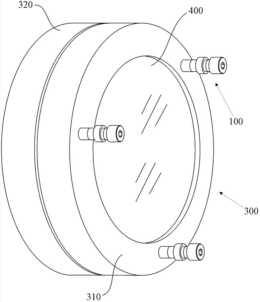
[0022] The spectacle frame fixing device proposed by the present invention will be described in further detail below in conjunction with the accompanying drawings and specific embodiments. Advantages and features of the present invention will be apparent from the following description and claims. It should be noted that the drawings are all in a very simplified form and use imprecise ratios, which are only used to facilitate and clearly assist the purpose of illustrating the embodiments of the present invention.

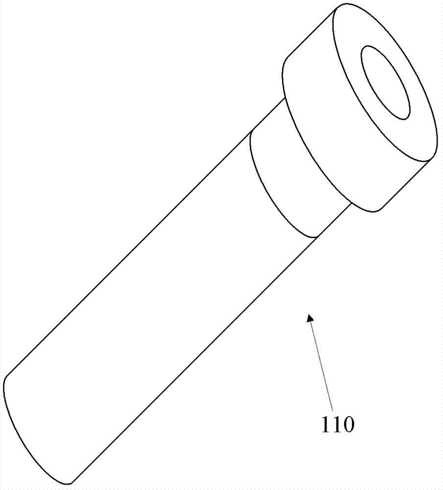
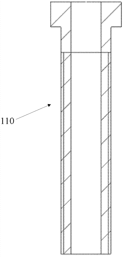
[0023] The core idea of ​​the present invention is to provide a frame fixing device, which is used to fix the upper frame and the lower frame in the objective lens frame of a lithography machine, the frame fixing device includes a screw fixing device, and the screw fixing device includes a screw sleeve and screws, the screw sleeve is provided with a sleeve external thread, and the upper frame is provided with a threaded hole with an internal thread corresponding to t...


PUM


Abstract

The invention provides an objective lens frame fixing device which is used for fixing an upper objective lens frame and a lower objective lens frame in a lithography machine objective lens frame. The objective lens frame fixing device comprises bolt fixing devices, wherein each bolt fixing device comprises a bolt sleeve and a bolt. Each bolt sleeve is provided with a sleeve external thread. The upper objective lens frame is provided with an upper thread hole with an internal thread corresponding to the external thread of each bolt sleeve. The length of each bolt sleeve is larger than the thickness of the upper objective lens frame. Each bolt sleeve is screwed in the upper thread hole in the upper objective lens frame. The lower end of each bolt sleeve is contacted with the upper surface of the lower objective lens frame. Each bolt penetrates through each bolt sleeve to be fixed in the lower objective lens frame. The objective lens frame fixing device is simple in structure, easy to install, high in installation efficiency, stable and firm. The objective lens frame fixing device cannot be deformed by the effect of the stress produced when each bolt is screwed, and a facial form of a lens and the quality of a lithography machine are guaranteed.

Description

technical field [0001] The invention relates to the field related to photolithography machine production, in particular to a mirror frame fixing device. Background technique [0002] In the front-end manufacturing equipment of large-scale semiconductor integrated circuits, the lithography machine is the most complex and demanding equipment. It integrates opto-mechanical and electrical technologies, and the objective lens is the core component and the heart of the lithography machine. Therefore, the design requirements for the objective lens are very high. [0003] At present, the imaging quality requirements of the objective lens are getting higher and higher, so the requirements for the surface shape of the lens are also getting higher and higher, which puts forward higher requirements for the fixing method of the frame in the design of the objective lens. At present, the use of screws to directly fix the objective lens frame is A common method is to adjust the inclination...

Claims


Application Information

Patent Timeline
Patent Type & Authority Applications(China)
IPC IPC(8): G02B7/00G03F7/20
Inventor 王健
Owner SHANGHAI MICRO ELECTRONICS EQUIP (GRP) CO LTD
Why Eureka
Eureka Blog
Learn More