A liquid crystal display and its narrow frame structure
A technology of liquid crystal display and narrow frame, which is applied in the direction of instruments, nonlinear optics, optics, etc. It can solve the problems of troublesome application of sealant, narrow frame, single appearance design, etc., so as to reduce the risk of glass breakage and prevent warping The effect of deforming and simplifying the work process
- Summary
- Abstract
- Description
- Claims
- Application Information
AI Technical Summary
Problems solved by technology
Method used
Image
Examples
Embodiment 1
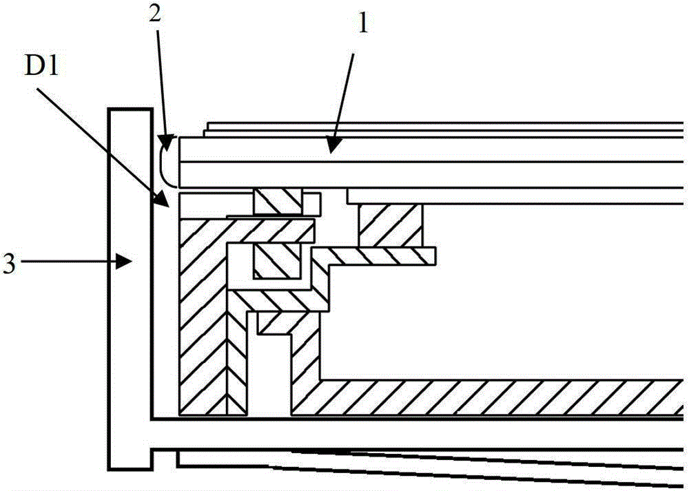
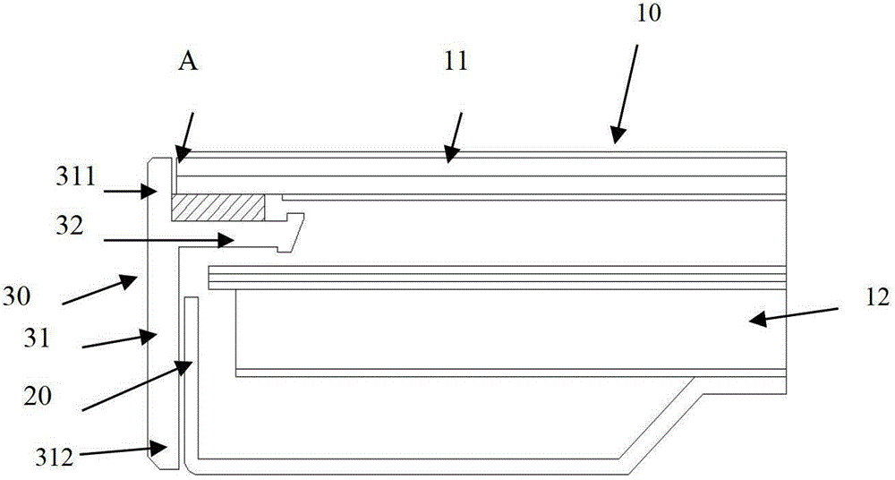
[0023] Such as figure 2 As shown, the liquid crystal display in this embodiment includes a liquid crystal display module 10 and a back frame 20, wherein the liquid crystal display module 10 is composed of a liquid crystal module 11 and a backlight module 12, and also includes a middle frame 30, wherein the middle frame 30 is fixed by side walls 31 and The horizontal wall 32 connected to the side wall 31 forms a T-shape. The horizontal wall 32 divides the side wall 31 into a front side wall 311 and a rear side wall 312. As shown in the figure, the liquid crystal module 11 is fixed on the horizontal wall 32 and its The side corresponds to the inner side of the front side wall 311, and can also be as figure 1 As shown, a sealant (not shown) is coated on the edge A of the liquid crystal module 11, wherein the liquid crystal module 11 is connected to the horizontal wall 32 of the middle frame 30 by pasting hair on the lower glass substrate 13 of the liquid crystal module 11. Bubb...
Embodiment 2
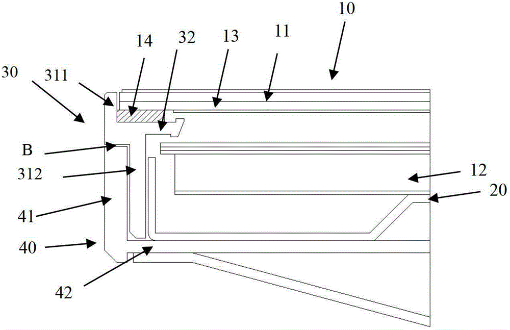
[0028] The structure of this embodiment is as image 3 As shown, different from Embodiment 1, the side wall 31 of the middle frame 30 is composed of an integrally formed front side wall 311 and an indented rear side wall 312, that is, the rear side wall 312 and the front side wall 311 form a step, and at the same time It also includes a side outer frame 40, the side outer frame 40 is composed of a side frame 41 and a bottom frame 42 which are integrally connected vertically, wherein the side frame 41 is connected to the step, and the bottom frame 42 is fixedly connected to the back frame 20 , the fixed connection method can be screw connection or riveting. In order to achieve an overall uniform visual effect, the outer surface of the side frame 40 in this embodiment is on the same plane as the outer surface of the front side wall 311 . This structural design can prevent the front side wall 311 from warping outward, because when the front side wall 311 is warped outward, it wi...
Embodiment 3
[0030] see Figure 4 This embodiment differs from Embodiment 2 in that the step of the middle frame 30 also includes a groove 33 indented in the direction of the front side wall 311 along the surface of the rear side wall 312, and correspondingly, the end of the side outer frame 40 is provided with There is a convex edge 43 . This structure can strengthen the combination of the side outer frame 40 and the middle frame 30 without misalignment and the like, and the effect on the front side wall 311 is the same as that of Embodiment 2, and will not be repeated here.
PUM
| Property | Measurement | Unit |
|---|---|---|
| thickness | aaaaa | aaaaa |
| thickness | aaaaa | aaaaa |
Abstract
Description
Claims
Application Information
 - R&D
- Intellectual Property
- Life Sciences
- Materials
- Tech Scout
- Unparalleled Data Quality
- Higher Quality Content
- 60% Fewer Hallucinations
Browse by: Latest US Patents, China's latest patents, Technical Efficacy Thesaurus, Application Domain, Technology Topic, Popular Technical Reports.
© 2025 PatSnap. All rights reserved.Legal|Privacy policy|Modern Slavery Act Transparency Statement|Sitemap|About US| Contact US: help@patsnap.com


