
Coder and decoder method, coder decoder and electronic equipment of picture layer and sharding layer

An encoding method and image layer technology, applied in image communication, television, electrical components, etc., can solve the problems of increasing network transmission pressure, sharpening of the encoding bit rate, and inability to differentiate and control by segments, so as to relieve network transmission pressure and improve resistance. Bit error performance, reducing the effect of bit rate surge

Active Publication Date: 2013-07-10
ZTE CORP
View PDF3 Cites 10 Cited by
  • Summary
  • Abstract
  • Description
  • Claims
  • Application Information

AI Technical Summary

Problems solved by technology

If the network transmission status changes during sequence encoding, the encoder cannot flexibly change the encoding strategy of whether LF crosses the fragmentation boundary
If a conservative strategy is adopted to always set loop_filter_across_slice_flag to 0 (that is, LF is never allowed to cross the slice boundary), then LF cannot be fully utilized to improve coding efficiency when the network transmission status is good
[0008] 2. Under the existing HEVC, the encoder can only re-initialize the SPS to change the parameter settings by inserting an instant refresh frame (IDR, Instantaneous Decoding Refresh) to achieve a compromise between anti-error performance and encoding efficiency
However, the newly inserted IDR frame and its subsequent encoded frames often bring about a sharp increase in the encoded bit rate, which further increases the pressure on network transmission.
[0009] 3. The encoder can use PPS to control the encoding process of one image or multiple images within a time period, but it cannot differentiate the slices in the image.
Therefore, even if the coded blocks using inter-frame prediction in the entire image are affected by the same or similar inter-frame error diffusion (recovery error), the encoder cannot use HEVC's existing control methods for the slices in the image. Differentiate control to obtain a better trade-off between coding efficiency and anti-error performance
[0011] Due to the above-mentioned limitations of the prior art, the encoding and decoding methods of the prior art cannot obtain a good compromise between encoding efficiency and anti-error performance

Method used


Image

  • Coder and decoder method, coder decoder and electronic equipment of picture layer and sharding layer
  • Coder and decoder method, coder decoder and electronic equipment of picture layer and sharding layer
  • Coder and decoder method, coder decoder and electronic equipment of picture layer and sharding layer

Examples


Embodiment 1

[0112] The SPS stream organization mode used by Embodiment 1 of the present invention is shown in Table 1 below:

[0113]

[0114] Table 1

[0115] In the SPS code stream organization mode shown in Table 1 above, the strikethrough indicates that the flag bit loop_filter_across_slice_flag is deleted in the SPS code stream organization mode.

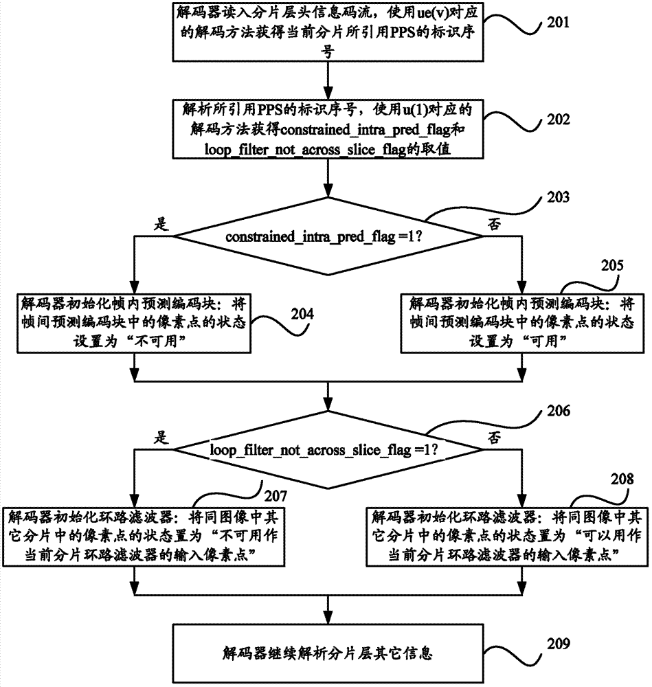
[0116] The PPS stream organization mode used in this embodiment is shown in Table 2 below:

[0117] pic_parameter_set_rbsp(){

Descriptor

……

constrained_intra_pred_flag

u(1)

loop_filter_not_across_slice_flag

u(1)

slice_granularity

u(2)

……

}

[0118] Table 2

[0119] In the above Table 2, the added loop_filter_not_across_slice_flag is used to identify whether the loop filter (DF, SAO, and ALF) is allowed to use the pixels of other slices in the image except the current decoding slice as the filter during the image decoding process. Input pixe...

Embodiment 2

[0157] The SPS code stream organization method used in this embodiment is the same as Table 1 in Embodiment 1.

[0158] The PPS stream organization mode used in this embodiment is as shown in Table 3 below:

[0159]

[0160] table 3

[0161] In the above Table 3, the strikethrough indicates that the flag bit constrained_intra_pred_flag is deleted in the organization mode of the PPS code stream. The added loop_filter_not_across_slice_flag is used to identify whether the loop filter (DF, SAO, and ALF) is allowed to use the pixels of other slices in the image except the currently decoded slice as the input pixels of the filter during the image decoding process. When the value of this flag bit is 1, during the decoding process of the image referencing the PPS, the loop filter does not use the pixels contained in other slices in the image except the current decoded slice as the input pixels of the filter ; When the value of this flag bit is 0, during the image decoding process...

Embodiment 3

[0198]The SPS code stream organization method used in this embodiment is the same as Table 1 in Embodiment 1.

[0199] The PPS code stream organization method used in this embodiment is the same as the existing method in HEVC, as shown in Table 5 below:

[0200] pic_parameter_set_rbsp(){

Descriptor

……

constrained_intra_pred_flag

u(1)

slice_granularity

u(2)

[0201] ……

}

[0202] table 5

[0203] The APS stream organization mode used in this embodiment is as shown in Table 6 below:

[0204] aps_rbsp(){

Descriptor

aps_id

ue(v)

aps_loop_filter_not_across_slice_flag

u(1)

……

}

[0205] Table 6

[0206] In the above Table 6, the added aps_loop_filter_not_across_slice_flag is used to identify whether the loop filter (DF, SAO, and ALF) is allowed to use pixels of other slices in the image as the input pixels of the filter duri...


PUM


Abstract

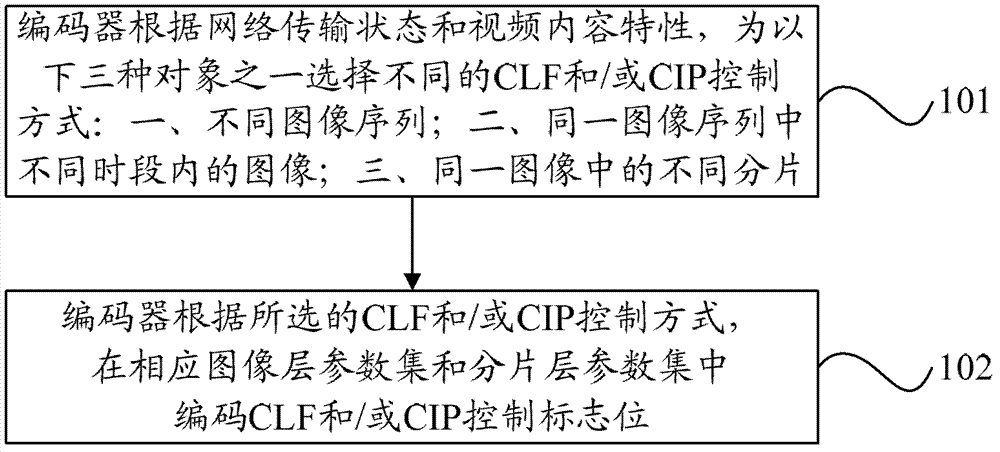
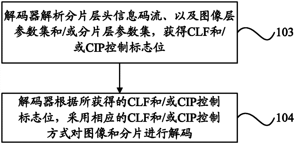
The invention discloses a coder and decoder method, a coder decoder and electronic equipment of a picture layer and a sharding layer. The coder and decoder method includes: selecting different limitation loop filtering model (CLF) and / or limitation intra-frame predicdion model (CIP) control manner for the following one of three objects: I, different image sequences; II, images in the same image sequence in different time intervals; III, different shardings in the same image according to network transmission states and video content features by an encoder; encoding CIF and / or CIP control zone bits in picture layer parameter sets and sharding layer parameter sets according to the selected CIF and / or CIP control manner; analyzing sharding layer information code stream, and the picture layer parameter sets and / or the sharding layer parameter sets by a decoder according to the obtained CIF and / or CIP control zone bits, using the corresponding CLF and / or CIP control manner to decode images and shardings. Good compromises between code efficiencies and error-code-resistant performances can be obtained through the coder and decoder method, the coder decoder and the electronic equipment of the picture layer and the sharding layer.

Description

technical field [0001] The invention relates to video compression coding technology, in particular to a codec method, codec and electronic equipment for image layer and slice layer. Background technique [0002] In video communication, in order to improve the anti-error ability of the video coded stream, the encoder usually uses an anti-error coding tool in the encoding process to reduce the mutual influence between the current coding unit and the coded unit, so that the receiving If there is an error in the relevant code stream of a certain coding unit, there is still a high possibility to use existing data to cover it up, and minimize the impact of the data of this coding unit on the decoding of subsequent coding units. [0003] Currently, the High-Efficiency Video Coding standard (HEVC, High-Efficiency Video Coding) uses a method of dividing an image into one or more slices (slices), so as to meet the limitation on the number of payload bits of a network transmission unit...

Claims


Application Information

Patent Timeline
Patent Type & Authority Applications(China)
IPC IPC(8): H04N7/26H04N21/845
CPCH04N19/172H04N19/46H04N19/117H04N19/164H04N19/174H04N19/82H04N19/70H04N19/107H04N19/14H04N19/137H04N19/159
Inventor 李明吴平
Owner ZTE CORP
Learn More