Forming method of iron core for movable iron unit

A molding method and iron core technology, applied in electrical components, sensors, etc., can solve the problems of difficult processing, high processing cost, and difficult to ensure processing accuracy, and achieve the effect of simple processing process, low processing cost, and guaranteed processing accuracy.

Active Publication Date: 2013-07-10
SUZHOU YICHUAN TECH CO LTD
View PDF3 Cites 2 Cited by
  • Summary
  • Abstract
  • Description
  • Claims
  • Application Information

AI Technical Summary

Problems solved by technology

This molding method has been found in use, because the one-time molding method has higher requirements for both the processing technology and the molds and processing equipment involved. For example, when pouring, special mold opening is required, and the casting Temperature, time, etc. need to be tested and stipulated, and when stamping, the molds involved are more complicated, and when drawing, the temperature, time, etc. involved also need to be tested and specified. The processing cost will be correspondingly higher, and the processing difficulty is obviously greater. For such a small device as the moving iron unit, the iron core is also small, so the precision requirement is higher, and the processing difficulty is increased. It is undoubtedly difficult to guarantee the machining accuracy

Method used


Image

  • Forming method of iron core for movable iron unit
  • Forming method of iron core for movable iron unit
  • Forming method of iron core for movable iron unit

Examples


Embodiment 1

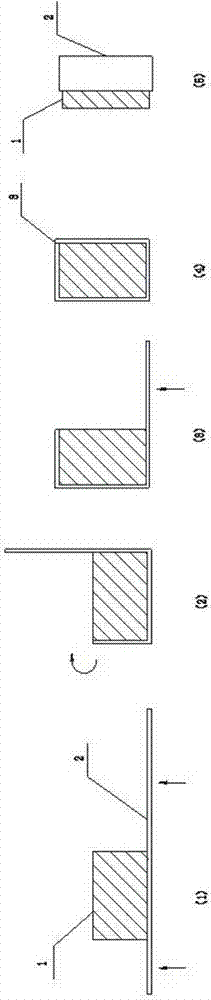
[0028] combine figure 1 As shown, the forming method of the iron core for the moving iron unit in the present embodiment may further comprise the steps:

[0029] (1) Prepare a piece of material 2 and a mold of kernels 1:

[0030] The length of the strip 2 is equal to the circumference and width of the outer ring of the iron core to be processed, and the width is equal to the axial length of the iron core to be processed, and the circumference of the outer ring of the mold core 1 is equal to the circumference and height of the inner ring of the iron core to be processed It is equal to the height of the inner ring of the iron core to be processed, and the axial length is at least equal to the axial length of the iron core to be processed;

[0031] (2) Punch the strip 2 through the punching equipment:

[0032] The mold core 1 is placed on the strip material 2, and the distance from it to one end of the strip material 2 is equal to the height of the mold core 1, and the strip ma...

Embodiment 2

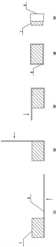
[0037] combine figure 2 As shown, the forming method of the iron core for the moving iron unit in this embodiment includes the same content as that of Embodiment 1, the difference lies in the included step 2), and this step 2) is: the mold core 1 is placed on the strip 2, the distance from one end of the strip 2 is equal to the height of the mold core 1, and the strip 2 is placed between the upper and lower molds of the punching equipment, such as figure 2 As indicated by the arrow, the two punching heads on the lower die punch the strip 2 along the mold core 1, and then turn the strip 2 and the mold core 1 by 90° through a turning device, and one punching head on the lower die continues Along the mold core 1 pair of strips 2 punching.

Embodiment 3

[0039] combine image 3 As shown, the forming method of the iron core for the moving iron unit in this embodiment includes the same content as that of Embodiment 1, the difference lies in the included step 2), and this step 2) is: the mold core 1 is placed on the strip 2, place the strip 2 between the upper and lower molds of the punching equipment, such as image 3 As indicated by the middle arrow, a punching head on a die in the lower die punches a pair of strips 2 along the core 1, and then places the strip 2 between a set of left and right dies perpendicular to the upper and lower dies , a punching head on the right die punches a pair of strips 2 along the mold core, and finally puts the strip 2 between the upper and lower dies, and a punching head on the upper die along the mold core 1 pair of strips Material 2 punching.


PUM


Abstract

The invention discloses a forming method of an iron core for a movable iron unit. The forming method of the iron core for the movable iron unit comprises the following steps: a strip material and at least one mould core are prepared, the length of the strip material is equal to the outer circle perimeter of at least one iron core needing to be machined, the width of the strip material is at least equal to the axial length of the iron core, the outer circle perimeter, the height and the axial length of the mould core are respectively equal to the inner circle perimeter, the height and the axial length of the needed iron core, the strip material is arranged between two moulds of punching equipment, the mould core is arranged on the strip material, a punch of the punching equipment punches the strip material in one or multiple directions along the outer circle of the mould core, the mould core is taken out of the punched iron core through manual work or a machine, and the mould core is fixedly connected at a breaking position of the punched iron core. By means of the forming method of the iron core for the movable iron unit, the machining cost and the machining difficulty can be lowered, and the machining accuracy is further guaranteed.

Description

technical field [0001] The invention relates to the technical field of moving iron units, in particular to a forming method of an iron core for a moving iron unit. Background technique [0002] In the structure of the moving iron unit, especially in the receiver, the iron core is a very important part, and its main function is to install magnets to form a magnetic circuit. The structure of the iron core is basically a hollow cylinder, and the magnet is installed on its inner ring. [0003] As for the processing and forming method of the iron core, the current processing method is basically one-time forming by means of die-casting, stamping or drawing. This molding method has been found in use, because the one-time molding method has higher requirements for both the processing technology and the molds and processing equipment involved. For example, when pouring, special mold opening is required, and the casting Temperature, time, etc. need to be tested and stipulated, and w...

Claims


Application Information

Patent Timeline
Patent Type & Authority Applications(China)
IPC IPC(8): H04R11/00
Inventor 梁皖渝张秀梅
Owner SUZHOU YICHUAN TECH CO LTD
Why Eureka
Try Eureka