
Hydraulic bench clamp and workpiece clamping method using same

A vise and hydraulic technology, applied in metal processing machinery parts, clamping, positioning devices, etc., can solve the problem of not being able to meet the batch processing requirements of various small precision workpieces, reduce the clamping time, and achieve uniform clamping force. , the effect of improving efficiency

Active Publication Date: 2013-07-17
SHENZHEN FLYTA TECH DEV
View PDF6 Cites 1 Cited by
  • Summary
  • Abstract
  • Description
  • Claims
  • Application Information

AI Technical Summary

Problems solved by technology

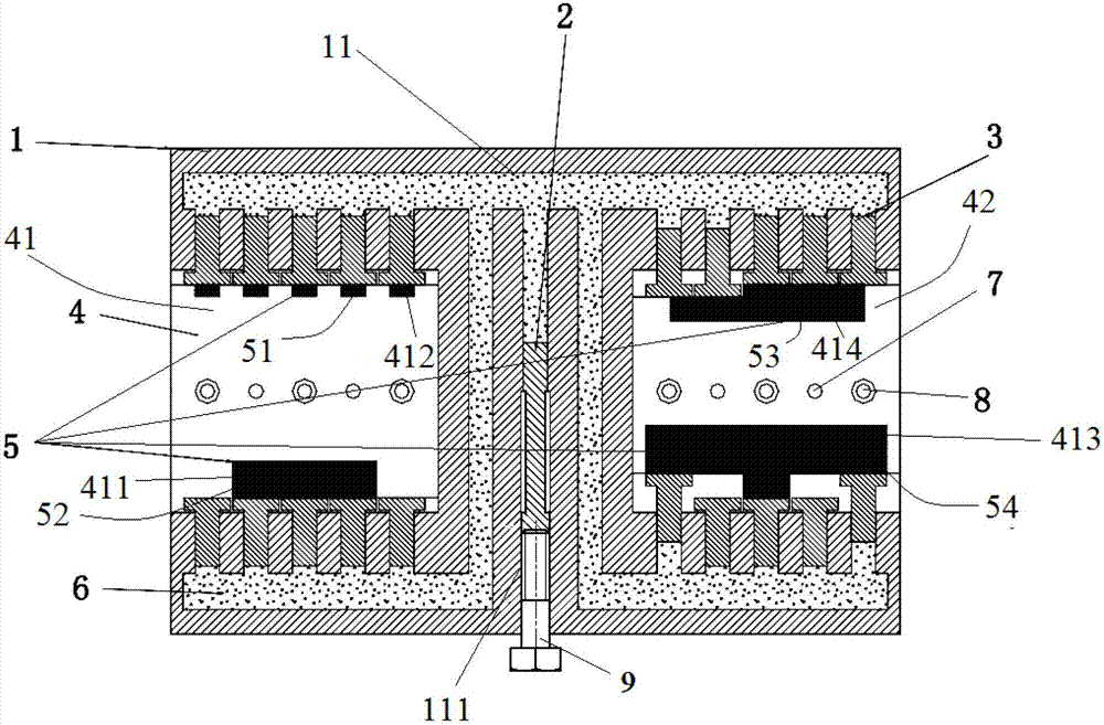
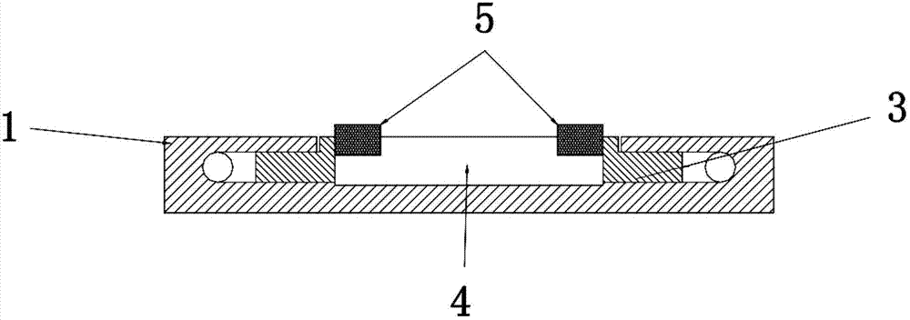
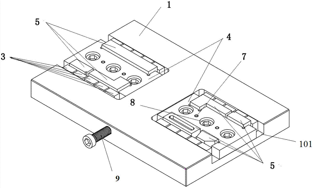
[0003] Aiming at the problem that the prior art cannot meet the batch processing requirements of various small precision workpieces, the present invention provides a hydraulic vise, which includes a vise main body 1 and a reciprocating push piston 2 placed inside the vise main body 1 , a plurality of reciprocating driven pistons 3 mounted on the main body 1 of the vice, and fixed jaws 4 fixed on the main body 1 of the vice; The hydraulic pipeline 11 of the hydraulic oil 6, the push piston 2 is installed and can reciprocate in the hydraulic pipeline 11; the hydraulic pipeline 11 is also provided with a plurality of openings outside the clamp main body 1, the multiple Two driven pistons 3 are installed respectively and can reciprocate at the plurality of openings, and the bottom end of each driven piston 3 extends into the hydraulic pipeline 11; The reciprocating motion in the pipeline 11 is transmitted to the plurality of driven pistons 3 through the hydraulic oil 6, driving the plurality of driven pistons 3 to reciprocate in the corresponding plurality of openings, so that the plurality of driven pistons The jaw faces of the two driven pistons 3 further extend into the fixed jaw 4 or withdraw from the fixed jaw 4 respectively.

Method used


Image

  • Hydraulic bench clamp and workpiece clamping method using same
  • Hydraulic bench clamp and workpiece clamping method using same
  • Hydraulic bench clamp and workpiece clamping method using same

Examples


Embodiment Construction

[0022] The present invention will be further described below in conjunction with the accompanying drawings and embodiments.

[0023] figure 1 , figure 2 and image 3 It shows a hydraulic vise provided by a preferred embodiment of the present invention, including a vise main body 1, a reciprocating push piston 2 placed inside the vise main body 1, a plurality of The reciprocating driven piston 3 on 1 and the fixed jaw 4 fixed on the main body 1 of the vise; the main body 1 of the vise is provided with a hydraulic pipeline 11 for filling hydraulic oil 6, the The push piston 2 is installed and can reciprocate in the hydraulic pipeline 11 . The hydraulic pipeline 11 is also provided with a plurality of openings outside the vise main body 1, and the plurality of driven pistons 3 are respectively installed at the plurality of openings and can reciprocate in the plurality of openings respectively, serving as The clamping head is used to clamp the workpiece 5 to be processed, and...


PUM


Abstract

The invention provides a multi-functional hydraulic bench clamp which comprises a vice bench body 1, a pushing piston 2, a plurality of driven pistons 3 and a fixing jaw which is fixed on the vice bench; the pushing piston which is arranged inside the vice bench body 1 is capable of performing reciprocating motion; the pushing pistons which are arranged inside the vice bench body 1 are capable of performing reciprocating motion; a hydraulic pipeline 11 which is used for holding hydraulic oil 6 is formed inside the vice bench body 1; the pushing piston 2 is arranged inside the hydraulic pipeline 11 and can perform reciprocating motion inside the hydraulic pipeline 11; positions of the hydraulic pipeline 11, which are outside the vice bench body 1, are provided with a plurality of openings; the plurality of driven pistons are arranged inside the he hydraulic pipeline 11 and can perform reciprocating motion inside the hydraulic pipeline 11; and bottoms of the driven pistons stretch into the hydraulic pipeline 11. The multi-functional hydraulic bench clamp has the advantages of achieving clamping of a plurality of small-sized workpieces at the same time and guaranteeing the clamping force the clamped workpieces bear is uniform and improving the efficiency of machining of the small-sized workpieces through a numerical control machine tool.

Description

technical field [0001] The invention relates to a clamping device, in particular to a hydraulic vise suitable for quickly clamping various small precision workpieces. Background technique [0002] At present, the hydraulic vise commonly used in metal cutting is large in size and is not suitable for clamping workpieces with small dimensions and irregular shapes, and generally can only clamp one workpiece at a time. It has a single function and low efficiency, which is difficult to meet Requirements for batch processing of various small precision workpieces. Contents of the invention [0003] Aiming at the problem that the prior art cannot meet the batch processing requirements of various small precision workpieces, the present invention provides a hydraulic vise, which includes a vise main body 1 and a reciprocating push piston 2 placed inside the vise main body 1 , a plurality of reciprocating driven pistons 3 mounted on the main body 1 of the vice, and fixed jaws 4 fixed...

Claims


Application Information

Patent Timeline
Patent Type & Authority Applications(China)
IPC IPC(8): B23Q3/08
Inventor 张赟汪欣
Owner SHENZHEN FLYTA TECH DEV
Learn More