Controllable electronic bulb for multi-line lamp string

A technology of electronics and street lamps, applied in the field of electronic bulbs, can solve the problems of large volume, poor working reliability, poor waterproof performance, etc., and achieve the effect of overcoming large volume

Inactive Publication Date: 2002-07-10
陈伟圣
View PDF0 Cites 0 Cited by
  • Summary
  • Abstract
  • Description
  • Claims
  • Application Information

AI Technical Summary

Problems solved by technology

[0004] The technical problem to be solved by the present invention is to provide an electronic bulb that can control multi-channel light strings. This electronic bulb that can control multi-channel light strings can be directly connected in series in the circuit circuit of multi-channel colorful lights. With a convenient

Method used


Image

  • Controllable electronic bulb for multi-line lamp string
  • Controllable electronic bulb for multi-line lamp string
  • Controllable electronic bulb for multi-line lamp string

Examples


Embodiment Construction

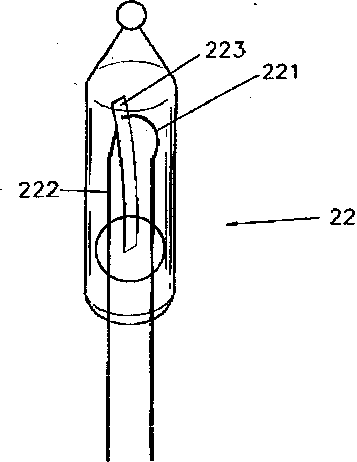
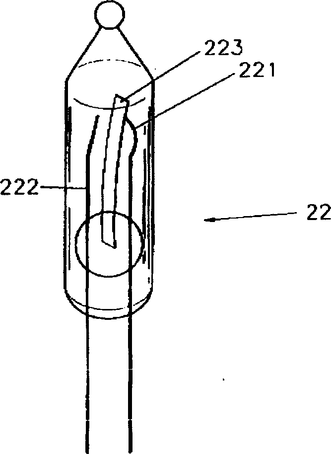
[0029] Figure 8 with Figure 9 It shows the circuit principle diagram, structure and external connection schematic diagram of the electronic bulb capable of controlling two-way colored light strings of the present invention. Such as Figure 8 As shown in the circuit, in the internal circuit of the electronic bulb that can control two colored light strings of the present invention, it includes a half-wave rectifier diode D1, two thyristor units (SCR) Q1, Q2, and the integrated circuit for controlling the colored light strings. circuit, the negative input terminal of the rectifier diode D1 is connected to one end of the external connection line 301 , and the other end of the connection line is connected to the power plug 305 . The colorful lamp control integrated circuit has two control output terminals b1 and b2 respectively connected to the control terminals of the thyristor Q1 and Q2, the integrated circuit is also connected with the third resistor R3, the first resistor R...


PUM


Abstract

The electric controller includes a lamp socket with inserted socket core, a controller body and several pieces of lamp wire, which are led out from the controller and stretched beyond the socket core. Inside the controller body, are installed color lamp controller IC, SCR, etc. and the output of the controller body is connected to multiple color lamp strings via wires and copper pins as well as outer wires. The electric controller controls automatically the on-off of several connected color lamp strings.

Description

technical field [0001] The present invention relates to electronic application technology, and more specifically, relates to a controllable multi-channel lighting system that can be directly connected in series in a circuit of colored lamp strings to control multiple strings of colored lights so that each string of colored lights emits and flickers according to a certain rule. Electronic bulbs for street light strings. Background technique [0002] The conventional connection mode of existing color light string (as Christmas color light string) is as shown in Figure 1, promptly is to connect each lamp holder (lamp cap) 20 on the power supply by electric wire 10, makes all be contained on the lamp holder 20 A plurality of bulbs 21 emit light together when the power is turned on. In order to achieve the light bulb flickering change effect, the prior art is realized in this way, in the circuit of the lamp holder 20 connected in series by the electric wire 10, a jump bulb 22 is...

Claims


Application Information

Patent Timeline
IPC IPC(8): F21S4/10F21S10/00H05B39/04
CPCY02B20/14Y02B20/00
Inventor 陈伟圣
Owner 陈伟圣
Why Eureka
Try Eureka