Balance mechanism of drilling and milling head of gantry movable type numerical-control drilling and milling machine

A mobile, drilling and milling machine technology, applied in the direction of metal processing machinery parts, other manufacturing equipment/tools, maintenance and safety accessories, etc., can solve the problems of increasing the power of the lifting spindle, the difficulty of replacing the wire rope, and the breakage of the wire rope, so as to reduce the driving force. force, ensure the stability and the effect of cutting machining accuracy

Inactive Publication Date: 2013-07-17
WUXI HUALIAN PRECISION MACHINERY
View PDF9 Cites 2 Cited by
  • Summary
  • Abstract
  • Description
  • Claims
  • Application Information

AI Technical Summary

Problems solved by technology

The disadvantage of this structure is that after the wire rope has been used for a period of time, the wire rope will be worn out. If it is not replaced in time, the wire rope will break. Since the counterweight mechanism does not have a self-locking mechanism, the wire rope will break, and the counterweight will fall to damage the bed of the machine tool, and the wire rope will break. It is difficult to replace the steel wire rope afterwards; if the counterweight is not used, the power of the lifting spindle must be increased because the lifting spindle of the power head bears a large force of gravity, which consumes more energy. On the other hand, the power The load on the head spindle is not uniform when it is raised and lowered, and the speed error generated during the movement will increase, resulting in machining accuracy errors

Method used


Image

  • Balance mechanism of drilling and milling head of gantry movable type numerical-control drilling and milling machine
  • Balance mechanism of drilling and milling head of gantry movable type numerical-control drilling and milling machine
  • Balance mechanism of drilling and milling head of gantry movable type numerical-control drilling and milling machine

Examples


Embodiment Construction

[0012] The specific implementation manner of the present invention will be described below in conjunction with the accompanying drawings.

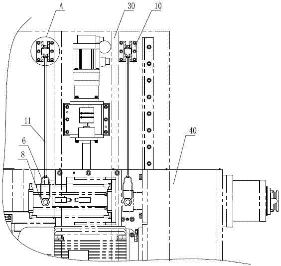
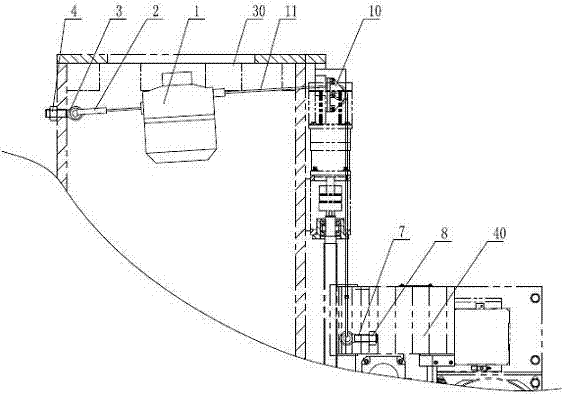
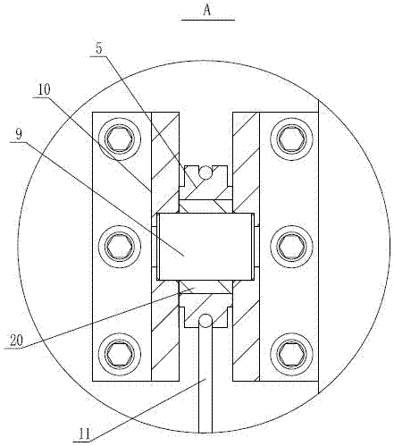
[0013] See figure 1 , figure 2 , the present invention includes a self-locking spring balancer 1, the two ends of the steel wire rope 11 in the body of the self-locking spring balancer 1 pass through the two sides of the housing of the self-locking spring balancer 1 respectively, and one side of the steel wire rope passes through the suspension The hook one 2 is connected to the joint of the joint bolt one 3, the joint bolt one 3 is fixed on the column assembly 30 through the nut one 4, and the steel wire rope on the other side passes through the connection between the hook two 6 and the joint bolt two 7 after winding around the roller 5 The joint is connected, and the joint bolt 2 7 is fixed on the drilling and milling head assembly 40 through the nut 2 8, and can move with the drilling and milling power head; see image 3 , the roller...


PUM


Abstract

A balance mechanism of a drilling and milling head of a gantry movable type numerical-control drilling and milling machine comprises self-locking spring balancers. Two ends of a steel wire rope in a body of each self-locking spring balancer respectively penetrate out of two sides of a shell of the self-locking spring balancer, the steel wire rope on one side of the shell of each self-locking spring balancer is connected with a connector of a first swing bolt by a first hook, the first swing bolts are fixed onto upright column assemblies by first nuts, the steel wire rope on the other side of the shell of each self-locking spring balancer is wound around a roller and then is connected with a connector of a second swing bolt by a second hook, and the second swing bolts are fixed onto a drilling and milling head assembly by second nuts and can move along with the drilling and milling head; and the rollers are sleeved on axles, the axles are fixed onto supports, the supports are fixed onto the upright column assemblies, and sliding sleeves are arranged among the rollers and the axles. The balance mechanism has the advantages that stress on the drilling and milling head can be balanced, driving force of a spindle of the drilling and milling head can be effectively relieved, and the running stability of the drilling and milling power head is guaranteed.

Description

technical field [0001] The invention relates to the technical field of numerical control drilling and milling equipment, in particular to a balance mechanism for balancing the weight of a drilling and milling power head and the drilling and milling force generated during drilling and milling in a gantry mobile numerical control drilling and milling machine. Background technique [0002] The CNC gantry drilling and milling machine is a processing equipment for large parts. The structure of the gantry mobile CNC drilling and milling machine is characterized by the movement of the gantry frame and the fixed worktable, so there is no limit to the weight of the workpiece, and super long parts can be processed. With its automation With the continuous improvement of performance and compounding degree, it has been widely used. In the gantry mobile CNC drilling and milling machine, the drilling and milling mechanism is usually equipped with a special counterweight structure to balanc...

Claims


Application Information

Patent Timeline
IPC IPC(8): B23Q11/00B23Q23/00
Inventor 陆松茂薛静清周敏铨武文邵燕瑛
Owner WUXI HUALIAN PRECISION MACHINERY
Why Eureka
Try Eureka