
Bias ply tire bead structure and carcass tire cord fabric reverse coating forming method

A technology of carcass cord and forming method, which is applied in the direction of tires, tire edges, tire parts, etc., can solve the problems of uneven force on the steel ring, shorten the service life of bias tires, and gas leakage, etc., to solve the problem of sidewall drum kit effect

Inactive Publication Date: 2013-07-17
SHANDONG LINGLONG TIRE
View PDF1 Cites 0 Cited by
  • Summary
  • Abstract
  • Description
  • Claims
  • Application Information

AI Technical Summary

Problems solved by technology

Due to the number of layers of bias ply tires with more than double steel rings, each steel ring is covered with outer cords, so the ends of the cords are all concentrated at the tire toe, especially in the design of the positive wrap tube. When the cord is wide or the front cord is biased upwards, it is very easy for the cord and the toe of the tire to protrude. When repairing the toe of the tire, the carcass cord will inevitably be cut off. In addition, even if the toe of the tire does not protrude On the other hand, when this kind of bias tire is in use, the gas in the carcass is also very easy to leak from the end of the cord at the tire toe, and because the cord is concentrated and accumulated at the bottom of the steel ring, there are too many layers of cord at the bottom of the steel ring, resulting in the steel ring being damaged. Uneven force, more likely to shorten the service life of bias tires

Method used


Image

  • Bias ply tire bead structure and carcass tire cord fabric reverse coating forming method
  • Bias ply tire bead structure and carcass tire cord fabric reverse coating forming method

Examples


Embodiment Construction

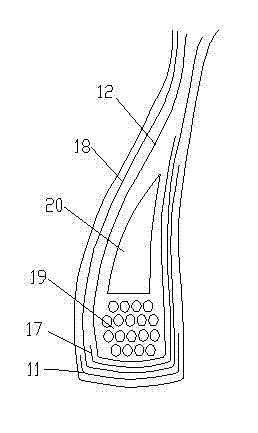
[0016] Please refer to figure 1 The bias tire bead structure according to the first embodiment of the present invention is shown, including a steel ring 19, an apex 20 adjacent to the steel ring 19, a first turn-up ply 12 surrounding the steel ring 11 and the apex 20, and a The front ply 17 outside the first turn-up ply 12, the outer turn-up ply 18 outside the front ply 17, and the toe pad rubber 11 arranged below the above-mentioned layers of ply.

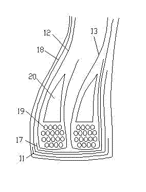
[0017] Please refer to figure 2 The bias ply tire bead structure according to the second embodiment of the present invention is shown, including two steel rings 19, two apex rubbers 20 adjacent to the two steel rings 19 respectively, and a first rubber apex 20 covering the two steel rings 19 and the apex rubber 20 respectively. A turn-up ply 12 and a second turn-up ply 13, while forward wrapping the positive wrap ply 17 at the bottom of the first and second turn-up ply 12, 13, reversely wrapping the outer ply 17 of the turn-up p...


PUM


Abstract

The invention discloses a bias ply tire bead structure and a carcass tire cord fabric reverse coating forming method. The bias ply tire bead structure comprises a steel ring, a bead filler, a first reverse coating cord fabric layer surrounding the steel ring and the bead filler, a right coating cord fabric layer surrounding the first reverse coating cord fabric layer, and a reverse coating cord fabric layer surrounding the right coating cord fabric layer. The carcass tire cord fabric reverse coating forming method provided by the invention comprises steps of: placing the bead filler; buckling a steel ring and compacting; using a the first cord fabric cylinder for converse pressure to form the reverse coating cord fabric; completing a right coating operation by another cord fabric cylinder; and finally conducting a reverse coating by the first cord fabric cylinder to form the reverse coating cord fabric, and padding a mat bead toe pad to complete production of tire bead. The tire bead structure prepared by the carcass tire cord fabric reverse coating forming method provided by the invention can avoid cutting of the tire cord thread during repair of border break of a multi-layer tire bead opening, and can solve a problem of sidewall bulge caused by gas penetration from carcass cord thread at tire toe.

Description

technical field [0001] The invention relates to a tire bead and a manufacturing method thereof, in particular to a bias tire bead and a carcass cord turn-up molding method. Background technique [0002] At present, bias tires are usually used in construction machinery with harsh operating conditions, heavy load capacity and long operating hours. Bias tires with many layers and more than double steel rings are generally formed by the sleeve method, and each steel ring must be turned up. Due to the number of layers of bias ply tires with more than double steel rings, each steel ring is covered with outer cords, so the ends of the cords are all concentrated at the tire toe, especially in the design of the positive wrap tube. When the cord is wide or the front cord is biased upwards, it is very easy for the cord and the toe of the tire to protrude. When repairing the toe of the tire, the carcass cord will inevitably be cut off. In addition, even if the toe of the tire does not ...

Claims


Application Information

Patent Timeline
Patent Type & Authority Applications(China)
IPC IPC(8): B60C15/00B29D30/18
Inventor 王锋宋肖英隋广震隋培兴任延春
Owner SHANDONG LINGLONG TIRE
Learn More