Novel bogie device for crane travelling mechanism

A technology of traveling mechanism and crane, which is applied in the direction of traveling mechanism, transportation and packaging, and load suspension components, etc. It can solve the problems that the wheels cannot be applied to the arc track, freely rotate, and cannot bear, so as to achieve a large overturning moment and increase safety. The effect of clearance and small form factor

Inactive Publication Date: 2013-07-17
SINOHYDRO JIAJIANG HYDRAULIC MACHINERY
View PDF10 Cites 3 Cited by
  • Summary
  • Abstract
  • Description
  • Claims
  • Application Information

AI Technical Summary

Problems solved by technology

[0010] 1. The traveling mechanism represented by the above-mentioned patent documents is not suitable for the gate hoist of the hydropower station with arc-shaped running track of the crane cart and other cranes with similar working conditions
[0011] 2. The traveling trolley on the traveling mechanism in the prior art cannot rotate freely in the horizontal plane, so in the actual use process, the phenomenon of "clamping rail" will occur, and it cannot bear large axial force, tilting moment and horizontal diameter. Xiang Li
[0012] 3. The wheels of the running mechanism in the prior art cannot be adapted to the radian of the arc track. Although there are also wheels with double rims, they still cannot better adapt to the hoist and the gate hoist of the hydropower station with arc-shaped operating track. Other cranes with similar working conditions

Method used


Image

  • Novel bogie device for crane travelling mechanism
  • Novel bogie device for crane travelling mechanism

Examples


Embodiment 1

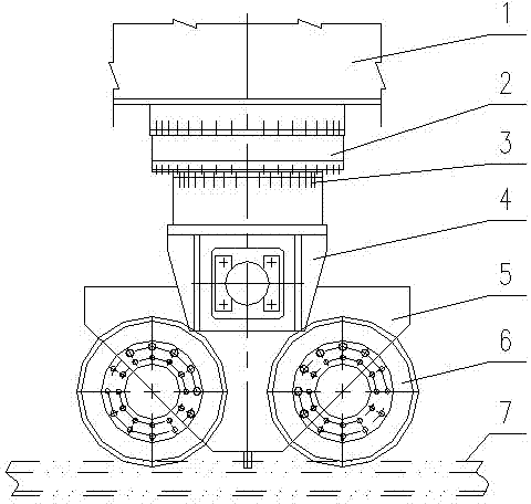
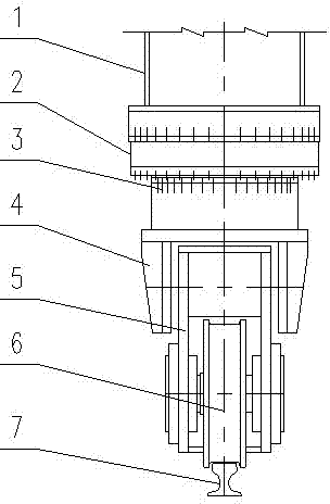
[0031] As a preferred embodiment of the present invention, the present invention discloses a new type of trolley device for crane traveling mechanism, including a trolley frame 5, traveling wheels 6 mounted on the trolley frame 5, a hinge seat 4, and an upper bracket 1. And the slewing support 2, the hinge base 4 is fixed on the trolley frame 5, and the slewing support 2 is connected between the hinge base 4 and the upper bracket 1. When the crane runs on the arc-shaped track, due to the track layout and crane installation When the wheel rim collides with the side of the curved track due to various reasons such as operation, the trolley rotates freely through the slewing bearing 2 under the action of horizontal horizontal force, thus avoiding the occurrence of jamming and effectively ensuring The traveling mechanism of the cart runs smoothly on the curved track. At the same time, the trolley can rotate freely in the horizontal plane, can withstand large axial forces, can withst...

Embodiment 2

[0033] As the best embodiment of the present invention, refer to the appendix of the specification figure 1 with 2 , The specific structure is: a three-row roller slewing support 2 is set between the hinge base 4 and the upper bracket 1 of the walking trolley, the slewing bearing 2 is placed horizontally, and the slewing bearing 2 is connected to the supporting hinge and the upper bracket 1. Bolted connection between. The walking wheel 6 of the gantry crane has a double rim, and the tread width of the wheel is 5-10 cm wider than that of a standard wheel to adapt to the curvature of the curved track. The trolley device has the following characteristics: the trolley can rotate freely in the horizontal plane, can withstand large axial forces, can withstand large tilting moments, and can withstand large horizontal radial forces, and has small dimensions; When traveling the trolley, place the centerline of the two wheel treads of the traveling trolley and the arc centerline of the t...


PUM


Abstract

The invention discloses a novel bogie device for a crane travelling mechanism, and relates to the technical field of hoisting machinery. The novel trolley device comprises a bogie frame, travelling wheels arranged on the bogie frame, a hinged support, an upper bracket and a slewing bearing, wherein the hinged support is fixed on the bogie frame; and the slewing bearing is connected between the hinged support and the upper bracket. The novel bogie device is better suitable for a headstock gear for a hydropower station gate with an arc-shaped crane cart running rail and other cranes with the similar working conditions, can guarantee the wheels not to be blocked by the rail, and effectively guarantees the crane travelling mechanism to stably run on the arc-shaped rail.

Description

[0001] Technical field [0002] The present invention relates to the technical field of hoisting machinery, and specifically to a mobile hoist suitable for hydraulic power station gates with large main hoisting capacity, main hoisting oblique pulling work, and arc-shaped trolley running track. The traveling mechanism of other cranes under similar conditions. Background technique [0003] In recent years, large-scale national hydropower construction projects are mostly concentrated in the mountainous valleys of western my country. Combined with the topographic characteristics of the power station dam site, the barrage dams often use concrete double-curved arch dams. The absolute height of the dams is very large. Above 200m, the hydrological situation is complicated during flood discharge, and the gate needs to be closed when the water is moving at critical times. The gate hoist arranged on the crest of the flood discharge dam has the following characteristics: [0004] 1. The main ho...

Claims


Application Information

Patent Timeline
Patent Type & Authority Applications(China)
IPC IPC(8): B66C9/16B66C9/04
Inventor 吴思够李启江
Owner SINOHYDRO JIAJIANG HYDRAULIC MACHINERY
Why Eureka
Try Eureka