
A mask plate for evaporation and its manufacturing process

A technology for manufacturing process and mask plate, which is applied in vacuum evaporation plating, metal material coating process, sputtering plating, etc., can solve the problem that the mask plate with large tapered opening cannot be made, so as to improve the precision and improve the position The effect of precision

Inactive Publication Date: 2015-11-25
KUN SHAN POWER STENCIL
View PDF3 Cites 0 Cited by
  • Summary
  • Abstract
  • Description
  • Claims
  • Application Information

AI Technical Summary

Problems solved by technology

[0008] The purpose of the present invention is to at least solve one of the above-mentioned technical defects, especially solve the problem that it is impossible to make a mask plate with a large tapered opening

Method used


Image

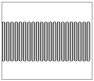
  • A mask plate for evaporation and its manufacturing process
  • A mask plate for evaporation and its manufacturing process
  • A mask plate for evaporation and its manufacturing process

Examples


Embodiment Construction

[0028] Embodiments of the present invention are described in detail below, examples of which are shown in the drawings, wherein the same or similar reference numerals designate the same or similar elements or elements having the same or similar functions throughout. The embodiments described below by referring to the figures are exemplary only for explaining the present invention and should not be construed as limiting the present invention.

[0029] In the description of the present invention, it should be understood that the orientation or positional relationship indicated by the terms "upper", "lower", "front", "rear", "inner", "outer" etc. Orientation or positional relationship is only for the convenience of describing the present invention and simplifying the description, and does not indicate or imply that the referred device or element must have a specific orientation, be constructed and operated in a specific orientation, and thus should not be construed as a limitation...


PUM


Abstract

The invention discloses a mask plate for vapor plating and a production method thereof, and the production method comprises the following steps of: arranging a substrate; electroforming at least two mask plate layers in order on one surface of the substrate, and each mask plate layer is arranged with openings, and the size of the openings of each mask plate layer is widened along with the distance from the mask plate layer to the substrate. A plurality layers of openings are arranged together to roughly be a cone shape. According to the mask plate for vapor plating and the production method thereof provided by the invention, through electroforming a plurality of mask plate layers, the position accuracy of the mask plate for OLED vapor plating is improved, the opening size accuracy of the mask plate for OLED vapor plating is improved, and the angles of upper and lower openings can be controlled at will to satisfy vapor plating requirements.

Description

technical field [0001] The invention belongs to the technical field of mask making, and relates to a mask structure, in particular to a mask for evaporation; meanwhile, the invention also relates to a manufacturing process of a mask for evaporation. Background technique [0002] The organic light emitting display has been paid great attention due to its advantages of wide viewing angle, high contrast ratio, and high response speed. Meanwhile, electroluminescent devices are classified into inorganic electroluminescent devices and organic electroluminescent devices; organic light-emitting devices have higher brightness and response speed than inorganic electroluminescent devices, and can display color images. [0003] An organic electroluminescence display includes an organic electroluminescence device having an anode, an organic material layer, and a cathode respectively stacked on a substrate. The organic material layer includes an organic emission layer that emits light du...

Claims


Application Information

Patent Timeline
Patent Type & Authority Patents(China)
IPC IPC(8): C23C14/04C23C14/24C25D1/10
Inventor 魏志凌高小平赵录军孙倩郑庆靓
Owner KUN SHAN POWER STENCIL
Learn More