
Radiating shell of LED lamp

A technology of heat dissipation shell and LED lamp, which is applied in the cooling/heating device of lighting device, lighting and heating equipment, semiconductor device of light-emitting element, etc. The effect of fast speed, smooth flow and increased heat dissipation area

Inactive Publication Date: 2013-07-17
GUANGDONG ECORISING TECH
View PDF3 Cites 13 Cited by
  • Summary
  • Abstract
  • Description
  • Claims
  • Application Information

AI Technical Summary

Problems solved by technology

In the existing design, only one or more of these factors are often considered, and some factors are not considered, which leads to the unreasonable heat dissipation structure of the design and the failure to achieve the best heat dissipation effect.

Method used


Image

  • Radiating shell of LED lamp
  • Radiating shell of LED lamp
  • Radiating shell of LED lamp

Examples


Embodiment Construction

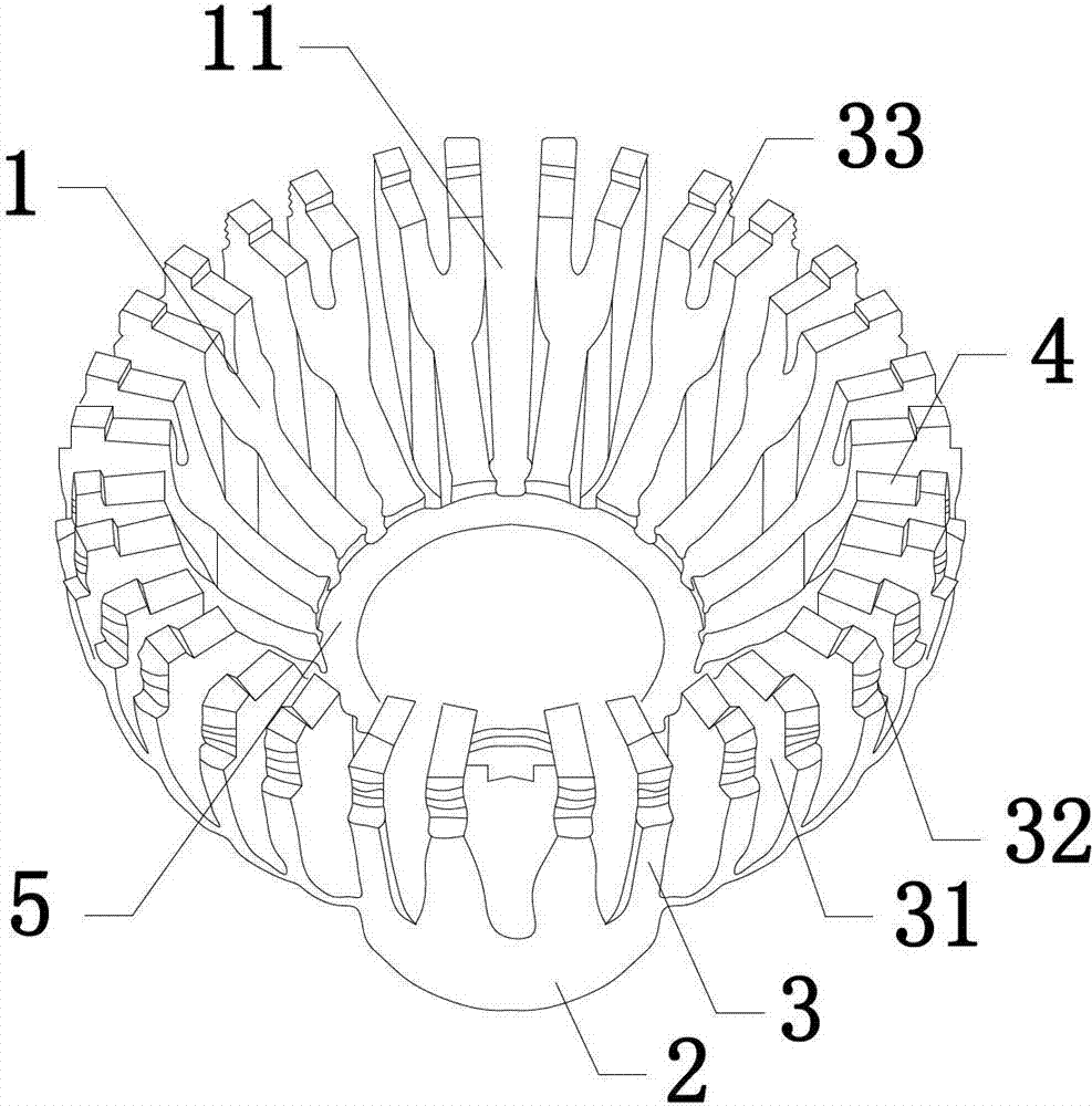
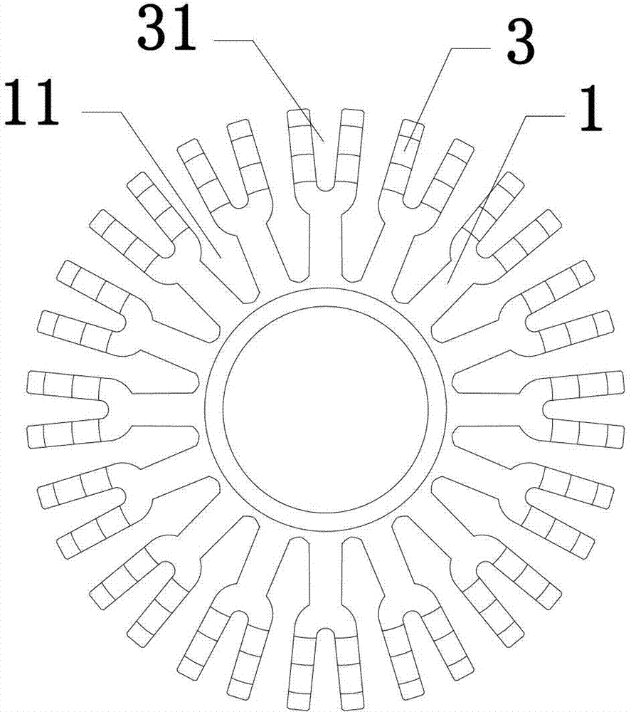
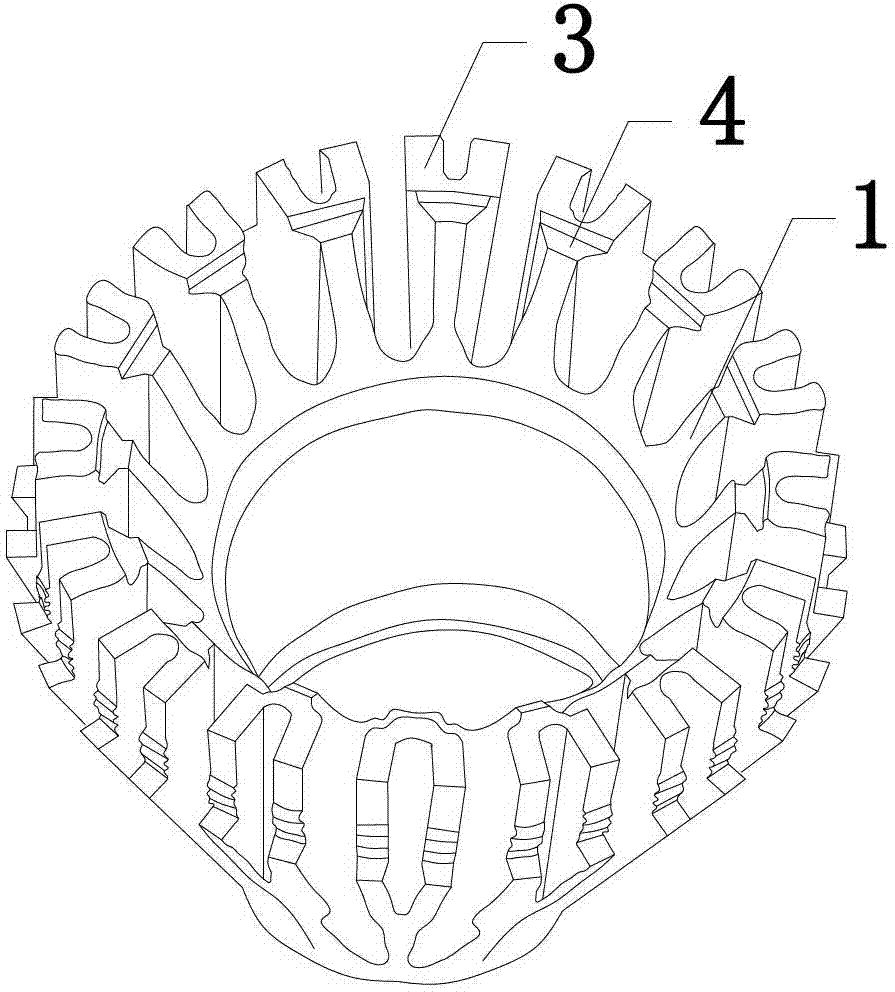
[0027] The first embodiment of the present invention is figure 1 and 2 As shown, it includes a plurality of cooling fins 1 and a tubular heat-absorbing core 2. The plurality of cooling fins 1 are arranged radially around the outer wall of the heat-absorbing core 2. Since each cooling fin 1 is arranged at intervals, adjacent cooling fins 1 There is a certain gap between them, which is defined as the main ventilation slot 11, wherein the cross section of the main ventilation slot 11 is U-shaped; in addition, the plurality of cooling fins 1 all extend to the same end of the heat-absorbing core 2, and This end forms a cavity for placing devices, the cavity is roughly bowl-shaped and communicates with multiple main ventilation slots 11 .

[0028] Furthermore, two radially arranged fins 3 are arranged on the outer side of each heat sink 1, and since the two fins 3 are arranged at intervals, there is a certain gap between the two fins 3, and the gap is defined as a secondary The ve...


PUM

PropertyMeasurementUnit
Thicknessaaaaaaaaaa
Thicknessaaaaaaaaaa

Abstract

The invention aims at providing a radiating shell for improving radiating efficiency of an LED lamp. The radiating shell comprises a tubular heat absorbing core and multiple radiating fins radially arranged around the heat absorbing core, a main ventilation groove is formed between each two adjacent radiating fins, the multiple radiating fins extend towards a same end of the heat absorbing core and form a cavity used for holding devices by surrounding at the end, the cavity and the main ventilation grooves are communicated, the outside of each radiating fin is at least provided with two radially-arranged fins, and auxiliary ventilation grooves are formed among the fins on a same radiating fin. The structure of the radiating shell is improved by additionally arranging the fins on the radiating fins, so that radiating effect of the radiating shell is greatly improved.

Description

technical field [0001] The invention relates to a heat dissipation shell, in particular to a heat dissipation shell applied to an LED lamp. Background technique [0002] With the development of society, energy saving and environmental protection have become the theme of the new era, but the traditional light source has high energy consumption, short life, and contains harmful substances such as mercury, which is difficult to meet the needs of social development, and the emergence of LED just solves this problem. kind of dilemma. Compared with traditional light sources, LED light sources are recognized as the most promising lighting source in the 21st century. Its advantages such as green environmental protection, long life, energy saving, high reliability, good light efficiency, and small size make LED light sources relatively traditional incandescent Lamps, fluorescent lamps, energy-saving lamps, etc. have greater application prospects. With the development of LED technol...

Claims


Application Information

Patent Timeline
IPC IPC(8): F21V29/00F21Y101/02F21V29/50F21V29/74F21V29/83F21Y115/10
Inventor 何峥张浩谢武华
Owner GUANGDONG ECORISING TECH
Learn More