
Pipeline liquid level sensor for mine

A liquid level sensor and pipeline technology, applied in the field of flow sensors, can solve the problems of liquid flow interference, damage, misjudgment, etc., and achieve the effects of stable working performance, safe and reliable use, and strong applicability

Active Publication Date: 2013-07-17
TIANDI CHANGZHOU AUTOMATION +1
View PDF7 Cites 0 Cited by
  • Summary
  • Abstract
  • Description
  • Claims
  • Application Information

AI Technical Summary

Problems solved by technology

The traditional mechanical flow detection device may interfere with the flow of the liquid because the sensor probe has moving firmware (such as a baffle) in the pipeline, and may even cause misjudgment or damage when the liquid is corrosive or dirty
The common device used to detect the liquid in the pipeline is a detection sensor that uses the principle of ultrasonic measurement or electromagnetic measurement. In the case of slow or static liquid, the measurement effect is very insignificant
The Chinese patent document with the publication number CN201764883U discloses a flow sensor. The flow sensor divides the annular cavity of the sensor into three closed and alternately changing volumes by setting a baffle plate and a rotor in the cavity. To measure the flow rate, its structure is relatively complex, the work reliability is not good, and when the liquid is in a static state, it is difficult to detect

Method used


Image

  • Pipeline liquid level sensor for mine
  • Pipeline liquid level sensor for mine
  • Pipeline liquid level sensor for mine

Examples


Embodiment 1)

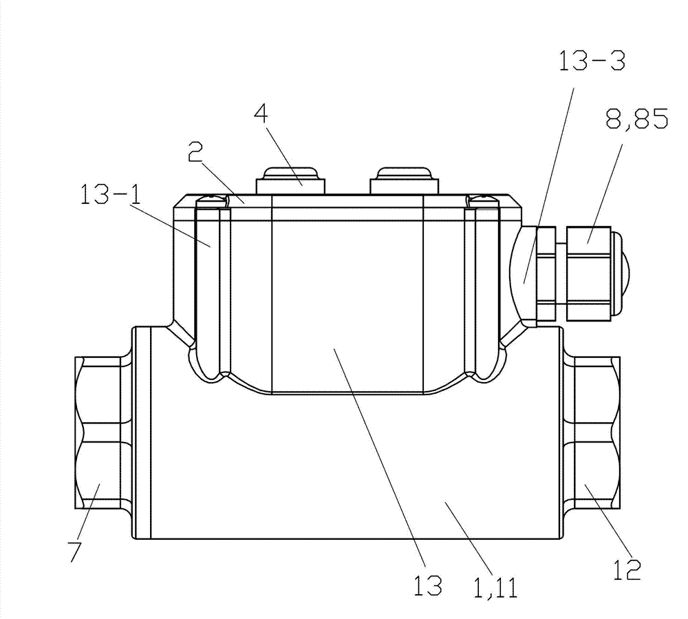
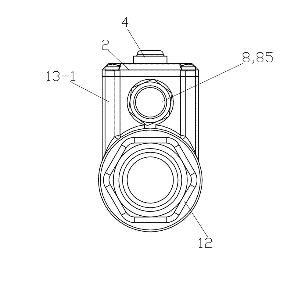
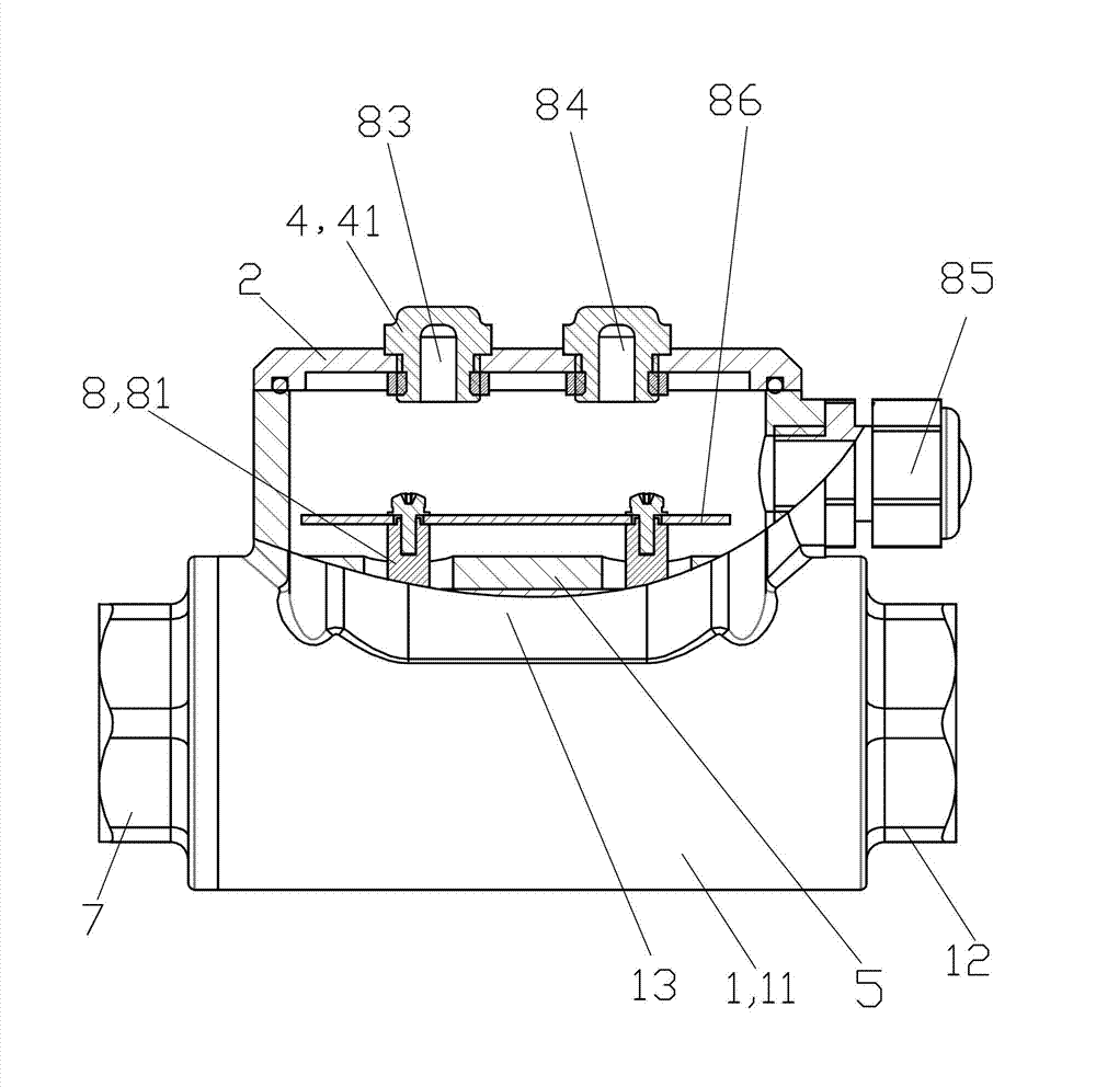
[0033] See Figure 1 to Figure 5 , The mine pipeline liquid level sensor of this embodiment is composed of a base body 1, a cover plate 2, a sealing assembly 3, a lampshade assembly 4, a lining 5, a fastener 6, an adapter assembly 7 and a circuit device 8.

[0034] The base body 1 is a cast stainless steel integral piece. The base body 1 is integrally composed of a cylindrical part 11 , a pipe connection part 12 and a mounting part 13 .

[0035] The cylinder portion 11 of the base body 1 is a hollow cylinder, and its upper end is provided with an opening consistent with the lower end opening of the installation portion 13, and the pipe connection portion 12 is arranged on the right end of the cylinder portion 11, and the pipe at the right end of the pipe connection portion 12 The inner wall is provided with an internal thread for connecting with the underground liquid pipeline, and the inner wall at the left end of the cylinder part 11 is provided with an internal thread for ...


PUM


Abstract

The invention provides a pipeline liquid level sensor for a mine. The pipeline liquid level sensor comprises a base body, a cover plate, a sealing assembly, a lampshade assembly, a liner, two fasteners, an adapter assembly and a circuit device, wherein the liner is a hollow cylindrical element, and two electrode bar inserting holes are arranged at the upper end of the liner; the circuit device comprises two electrode bars, two electrodes, a power indicator light, an outgoing nozzle and a printed circuit board (PCB); electrode bar inserting holes are arranged at the upper ends of the electrodes; the two electrodes and the two fasteners are arranged in the liner, the two electrode bars and the two electrodes are connected in an inserting mode, and the liner is installed in the base body; the adapter assembly and the base body are fixedly connected in a sealing mode; the lampshade assembly is mounted on the cover plate, and the indicator light is arranged in the lampshade assembly; the base body and the cover plate are fixedly connected in a sealing mode; the outgoing nozzle and the base body are fixedly connected; and the PCB is provided with a signal amplification circuit, a sensitivity adjusting circuit, a single chip microcomputer control circuit and an output control circuit. The pipeline liquid level sensor is convenient to measure liquid levels in pipelines, high in accuracy, adjustable in sensitivity, safe, reliable and capable of meeting requirements of mine severe environments.

Description

technical field [0001] The invention relates to the technical field of flow sensors, in particular to a pipeline liquid level sensor used for underground detection of the liquid level in a pipeline. Background technique [0002] At present, there has been no corresponding effective means for judging whether there is liquid in the underground pipeline of the mine. The traditional mechanical flow detection device may interfere with the liquid flow because the sensor probe has moving firmware (such as a baffle) in the pipeline, and may even cause misjudgment or damage when the liquid is corrosive or dirty. The common device used to detect the liquid in the pipeline is a detection sensor that uses the principle of ultrasonic measurement or electromagnetic measurement. In the case of slow or static liquid, the measurement effect is very insignificant. The Chinese patent document with the publication number CN201764883U discloses a flow sensor. The flow sensor divides the annula...

Claims


Application Information

Patent Timeline
IPC IPC(8): G01F23/22
Inventor 李庆昭蒋军庭陈家财崔怀兵蒋伟宋海军
Owner TIANDI CHANGZHOU AUTOMATION
Learn More