
Non-contact current detection device of building fire-fighting equipment

A current detection device and fire-fighting equipment technology, which is applied in the direction of measuring devices, measuring current/voltage, measuring electricity, etc., can solve problems such as complicated and troublesome detection methods, and achieve the effect of simplifying detection methods

Active Publication Date: 2013-07-17
广东建筑消防设施检测中心有限公司
View PDF4 Cites 0 Cited by
  • Summary
  • Abstract
  • Description
  • Claims
  • Application Information

AI Technical Summary

Problems solved by technology

[0002] In the past, the non-contact current detection device of building fire protection equipment needed to put the detection ring outside the line to be tested, which made the detection method complicated and troublesome

Method used


Image

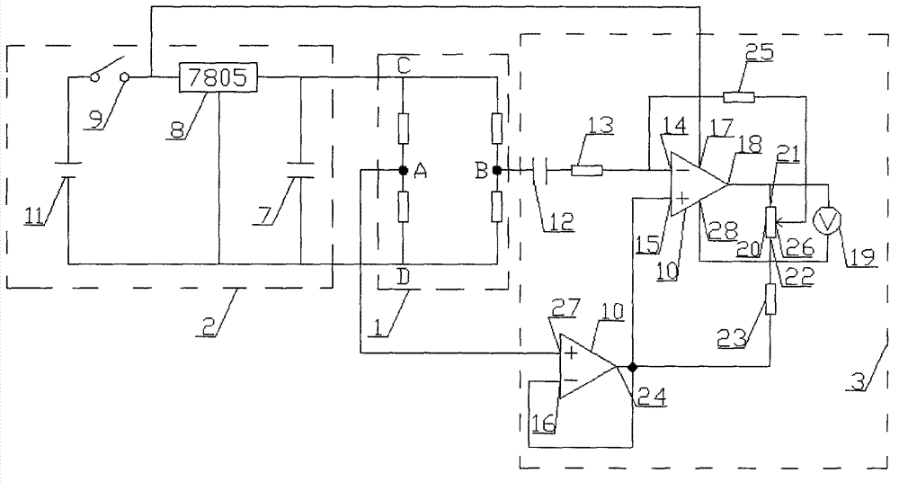
  • Non-contact current detection device of building fire-fighting equipment
  • Non-contact current detection device of building fire-fighting equipment

Examples


Embodiment approach

[0010] See figure 1 , figure 2 , the C end of the bridge circuit [that is, the detection end (1)] is connected with one end of the capacitor (7) of the power circuit (2) and the output end of the three-terminal integrated voltage regulator circuit (8), and the three-terminal integrated voltage regulator circuit (8) ) input terminal is connected with one end of the switch (9) and the power supply positive terminal (17) of the integrated operational amplifier (10), the other end of the switch (9) is connected with the positive terminal of the power supply (11), and the D terminal of the bridge circuit is connected with the positive terminal of the power supply (11). The other end of the capacitor (7) is connected to the common end of the three-terminal integrated voltage stabilizing circuit (8) and the negative end of the power supply (11); the B end of the bridge circuit is connected to one end of the capacitor (12) of the amplifying circuit (3), The other end of the capacito...


PUM


Abstract

The invention relates to a non-contact current detection device of building fire-fighting equipment and aims to enable the non-contact current detection device to perform detection near a detected line. The non-contact current detection device of the building fire-fighting equipment is characterized in that a detection end (1) is respectively connected with a power circuit (2) and an amplification circuit (3). The non-contact current detection device of the building fire-fighting equipment has the advantage that a detection mode of the non-contact current detection device is simplified.

Description

Technical field: [0001] The patent of the present invention relates to a non-contact current detection device for building fire protection equipment. Background technique: [0002] In the past, the non-contact current detection device of building fire protection equipment needs to put the detection ring outside the line to be tested, which makes the detection method complicated and troublesome. Invention content: [0003] The purpose of the patent of the present invention is to change the non-contact current detection device so that the detection device can be detected close to the detected line. The terminal (1) is respectively connected with the power supply circuit (2) and the amplification circuit (3). The connection with the power supply circuit (2) can ensure the power supply of the detection device, and the connection with the amplification circuit (3) can amplify the detected weak current for observation. [0004] The patent of the present invention can also be i...

Claims


Application Information

Patent Timeline
IPC IPC(8): G01R19/00G01R1/30
Inventor 蔡南贤汤永光王志锟孙毅钦杨卫强刘伟涛赵佩华宋立巍
Owner 广东建筑消防设施检测中心有限公司
Learn More