
Method for automatically detecting touch key state and display device

An automatic detection and display device technology, applied in the direction of circuit breaker testing, etc., can solve problems such as inconvenient maintenance, complicated touch key sensitivity parameter setting and verification steps, and hidden quality problems, so as to improve market quality and facilitate market maintenance , Improve the effect of process capability

Active Publication Date: 2013-07-17
TPV ELECTRONICS (FUJIAN) CO LTD
View PDF6 Cites 2 Cited by
  • Summary
  • Abstract
  • Description
  • Claims
  • Application Information

AI Technical Summary

Problems solved by technology

[0002] The touch button function is more and more used in various display devices, gradually replacing ordinary buttons. The touch button sensitivity parameter setting and verification steps are very complicated and imprecise
In the prior art, it is necessary to remove the touch button module during testing, connect it to the test fixture, connect the test fixture to the PC, and then use the PC to read the button value and the trigger value designed by the software to determine Whether the design value of the button is within the design expectation, this method is too complicated to operate, and the value cannot be read in the whole machine, there is a large quality risk
[0003] In the prior art, there is no simple, fast, accurate, and intuitive method for reading the sensitivity and signal-to-noise ratio of the touch keys, resulting in reduced efficiency and hidden dangers in quality; the prior art has the following disadvantages:
[0004] 1. In the design stage of the touch button, it is impossible to intuitively judge whether the design value of the button is within the design expectation;
[0005] 2. Reliability experiments rely on human operations to determine, and there are unpredictable risks;
[0006] 3. It is impossible to obtain the process capability of touch buttons in the production of touch button display devices;
[0007] 4. Defective modules cannot be determined during after-sales service in the terminal market, and cannot be easily repaired

Method used


Image

  • Method for automatically detecting touch key state and display device

Examples


Embodiment Construction

[0024] In order to make the object, technical solution and advantages of the present invention clearer, the present invention will be further described in detail below through specific embodiments and related drawings.

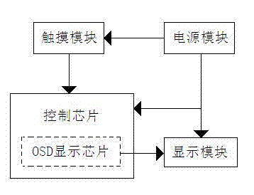
[0025] The present invention provides a method for automatically detecting the state of a touch button, which is characterized in that: a control chip is provided to connect with a touch module to convert the touch button signal sent by the touch module into signal-to-noise ratio and sensitivity; a display module is provided Connect the control chip to display the signal-to-noise ratio and sensitivity.

[0026] In a preferred embodiment of the present invention, the touch module communicates with the control chip through the I2C protocol. The touch key signal includes a maximum value and a noise value of the key signal of the touch module. The signal-to-noise ratio is equal to a ratio between the maximum value and the noise value, and the sensitivity is equal...


PUM


Abstract

The invention relates to the field of display, in particular to a method for automatically detecting a touch key state and a display device. The method is characterized in that a control chip is provided to be connected with a touch module so as to be used for converting touch key signals sent by the touch module into a signal-noise ratio and sensitivity; and a display module is provided to be connected with the control chip so as to display the signal-noise ratio and the sensitivity. The touch key signals are converted into the sensitivity and the signal-noise ratio to be displayed on a factory menu of the display device through an on-screen display (OSD) display chip of the control chip, so that the operators can visually read data of keys through the factory menu.

Description

technical field [0001] The invention relates to the display field, in particular to a method for automatically detecting the state of a touch key and a display device. Background technique [0002] The touch button function is more and more used in various display devices, gradually replacing ordinary buttons. The touch button sensitivity parameter setting and verification steps are very complicated and imprecise. In the prior art, it is necessary to remove the touch button module during testing, connect it to the test fixture, connect the test fixture to the PC, and then use the PC to read the button value and the trigger value designed by the software to determine Whether the design value of the button is within the design expectation, this method is too complicated to operate, and it is impossible to read the value in the whole machine, which has a large quality risk. [0003] In the prior art, there is no simple, fast, accurate, and intuitive method for reading the sens...

Claims


Application Information

Patent Timeline
IPC IPC(8): G01R31/327
Inventor 林海亮余何保陈育加
Owner TPV ELECTRONICS (FUJIAN) CO LTD
Learn More