
Optical angle reflection target ball and manufacturing method thereof

A manufacturing method and corner reflection technology, which is applied in optics, optical components, instruments, etc., can solve the problems that the concentricity of the glass reflector is difficult to achieve high precision, the installation process of the three reflecting surfaces is complicated, and the manufacturing cost of the glass reflector is high. Achieve the effects of improving structural firmness and drop resistance, simple structure, and low manufacturing cost

Inactive Publication Date: 2013-07-17
ACAD OF OPTO ELECTRONICS CHINESE ACAD OF SCI +1
View PDF9 Cites 5 Cited by
  • Summary
  • Abstract
  • Description
  • Claims
  • Application Information

AI Technical Summary

Problems solved by technology

[0005] 1. The concentricity between the corner point of the glass reflector and the sphere is difficult to achieve high precision, which affects the measurement accuracy
[0006] 2. The installation process of the three reflective surfaces is complicated, and the verticality is difficult to guarantee
[0007] 3. When the ambient temperature changes, the glass reflective surface is easily deformed
[0008] 4. The reflective ball is easily damaged when it falls
[0009] 5. Glass reflectors are expensive to manufacture

Method used


Image

  • Optical angle reflection target ball and manufacturing method thereof
  • Optical angle reflection target ball and manufacturing method thereof
  • Optical angle reflection target ball and manufacturing method thereof

Examples


Embodiment Construction

[0033] Specific embodiments of the present invention will be described in detail below in conjunction with the accompanying drawings.

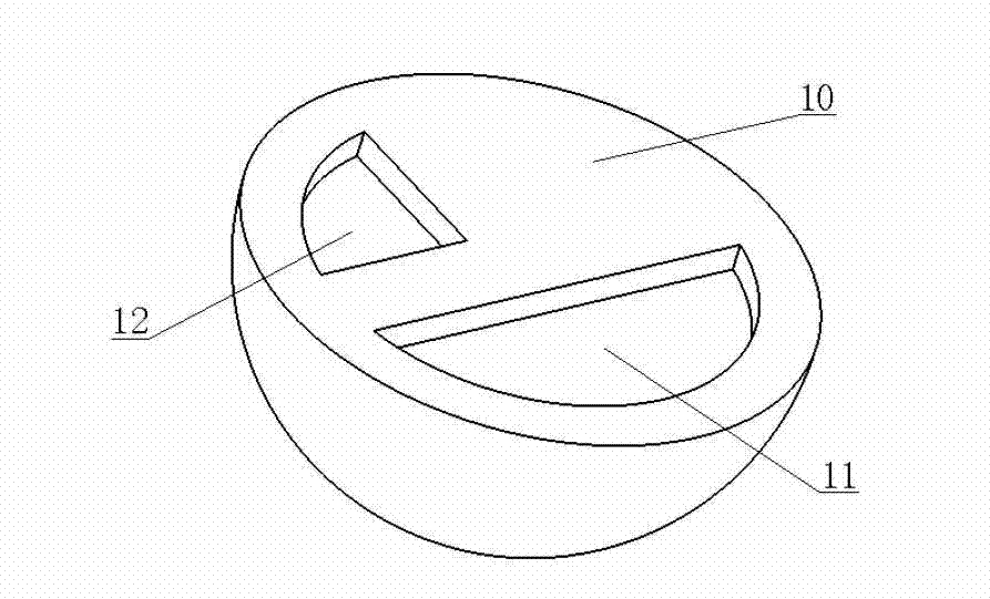
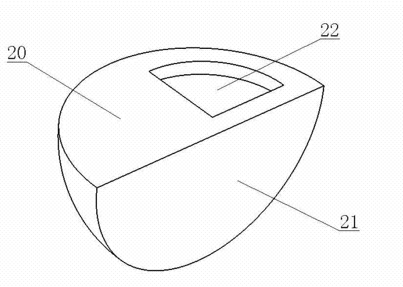
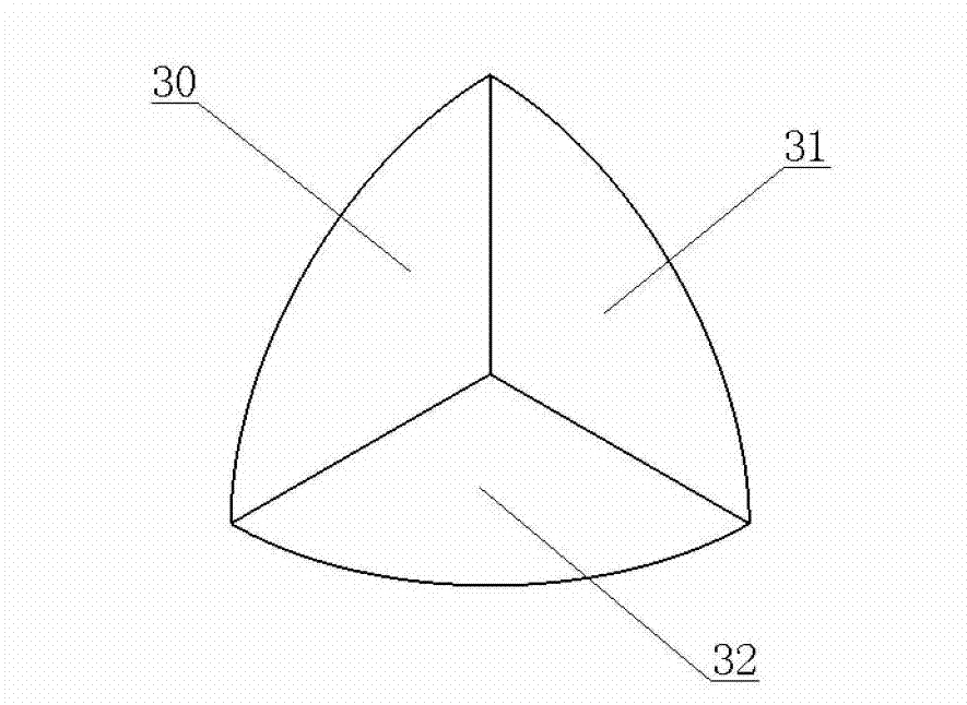
[0034] A processing method of the optical angle reflective target ball of the present invention is introduced below, and the specific steps of the method are as follows. First take a solid metal sphere, cut it in half three times in turn, and get a 1 / 2 metal sphere respectively (such as figure 1 shown), a 1 / 4 metal sphere (as figure 2 shown) and two 1 / 8 metal spheres (as image 3 shown), a 1 / 8 sphere is discarded. Such as figure 1 , 2 , 3, in the 1 / 2 metal sphere, 1 / 4 metal sphere, and 1 / 8 metal sphere, three reflective surfaces 10, 20, 30 are formed; three groups of corresponding bonding surfaces are also formed: bonding Surface 11 and bonding surface 21; bonding surface 12 and bonding surface 31; bonding surface 22 and bonding surface 32. Next, dig grooves on one of the two faces of each group of corresponding joint surfaces and apply...


PUM


Abstract

The invention provides an optical angle reflection target ball which is an integrated structure of an angle reflector and a ball body and is a seven-eighths ball body. Three reflection surfaces which are perpendicular to each other are formed at the position where a one-eighth ball body is lacked, the seven-eighths ball body is an all-metal structure, and the three reflection surfaces are polishing and coating surfaces. A manufacturing method of the optical angle reflection target ball is further provided. The angle reflector and the ball body are formed synchronously. The manufacturing method includes the following steps: shaping a solid metal ball body in a processing mode; performing three-time half-and-half cutting, obtaining a one / second metal ball body, a one / fourth metal ball body and two one / eighth metal ball bodies respectively, removing a one / eighth ball body, and forming three reflection surfaces and three groups of corresponding junction surfaces in the one / second metal ball body, the one / fourth metal ball body and the one / eighth metal ball body; performing polishing and coating on the three reflection surfaces; and combining each group of corresponding junction surfaces in a fixed mode, forming the seven / eighths ball body, and forming the three reflection surfaces which are perpendicular to each other. The optical angle reflection target ball is high in target ball accuracy, simple in structure, low in cost, firm and durable and strong in anti-fall capacity.

Description

technical field [0001] The invention relates to an optical angle reflection device and a manufacturing method thereof. The device is mainly used for laser tracking measurement and can also be used for other optical measurement systems. Background technique [0002] With the advancement of science and technology and the development of the equipment manufacturing industry, the requirements for laser trackers are getting higher and higher. Laser trackers have the characteristics of large measurement range, high precision, good dynamic performance, and real-time on-site measurement. It can not only perform high-precision three-dimensional measurement of space static targets, but also track and measure moving targets. It has been widely used in high-end intelligent manufacturing industries such as aerospace, rail transit, and shipbuilding. [0003] The tracking target ball, that is, the optical angle reflection target ball, is an important part of the laser tracker. The existing...

Claims


Application Information

Patent Timeline
IPC IPC(8): G02B5/122G02B1/00
Inventor 周维虎董岚劳达宝董登峰纪荣袆袁江张滋黎刘鑫丁蕾崔成君
Owner ACAD OF OPTO ELECTRONICS CHINESE ACAD OF SCI
Learn More