A polarizer and a display device

A polarizer and polarizing layer technology, applied in the field of polarizers and display devices, can solve the problems of incomplete absorption and light leakage, and achieve the effect of improving outdoor readability and reducing reflection

Active Publication Date: 2015-09-16
BOE TECH GRP CO LTD
View PDF9 Cites 1 Cited by
  • Summary
  • Abstract
  • Description
  • Claims
  • Application Information

AI Technical Summary

Problems solved by technology

[0009] like Image 6 As shown, when the external ambient light is incident on the circular polarizer along the direction with the azimuth angle of 0° and the polar angle of about 60°, that is, when viewed from an oblique direction of the circular polarizer, the direction of the transmission axis of the polarizer There is no deflection, and it is still perpendicular to the intersection of the positive direction of the S1 axis and the circumference, while the direction of the optical axis 703A of the quarter-wave plate is deflected. In this case, the light incident on the circular polarizer is reflected by the electrode layer and passes through the The circular polarizer cannot be completely absorbed, resulting in light leakage; according to the symmetry of the optical structure, when the azimuth angles are 90°, 180° and 270°, light leakage will also occur
[0010] like Figure 7 As shown, when the external ambient light is incident on the circular polarizer along the direction of the azimuth angle of 45° and the polar angle of about 60°, that is, when viewed from another oblique direction of the circular polarizer, the quarter wave plate The direction of the optical axis 703A is not deflected, and still coincides with the S2 axis, while the direction of the transmission axis of the polarizing layer is deflected, that is, the transmission axis of the polarizing layer is still perpendicular to point A, but point A has changed from the S1 axis The intersection of the positive direction and the circumference deviates, which will also cause light leakage in this case; according to the symmetry of the optical structure, when the azimuth angles are 135°, 225° and 315°, light leakage will also occur

Method used


Image

  • A polarizer and a display device
  • A polarizer and a display device
  • A polarizer and a display device

Examples


Embodiment 1

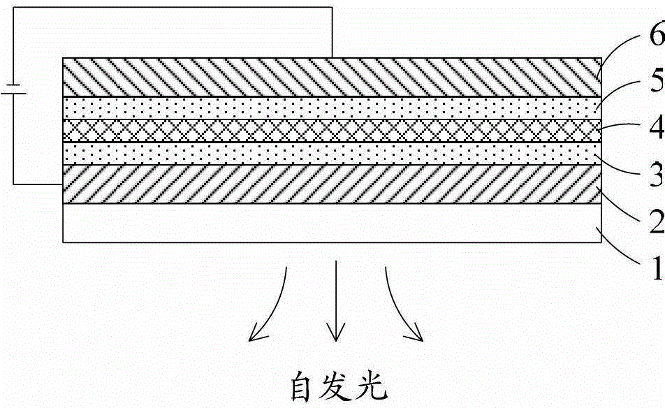
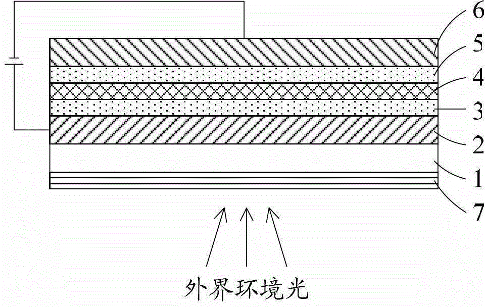
[0056] This embodiment provides a polarizer, which is used in conjunction with a reflective layer. The polarizer includes a polarizer layer and a compensation layer. The compensation layer is arranged between the polarizer layer and the reflective layer, and incident to the polarizer The light incident on the compensation layer is absorbed by the absorption axis of the polarizing layer and then enters the compensation layer. The compensation layer and the reflective layer cooperate to convert the light incident on the compensation layer into a line whose polarization direction is consistent with the absorption axis direction of the polarizing layer. Polarized light is thus absorbed by the polarizing layer. The reflective layer can be made of any material capable of reflecting light, for example, it can be an electrode layer in an OLED display device.

[0057] That is to say, the light incident on the polarizer along various directions passes through the absorption axis absorpt...

Embodiment 2

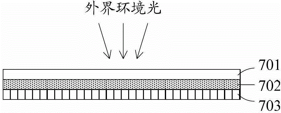
[0061] Such as Figure 8 As shown, this embodiment provides a polarizer, which is used in conjunction with a reflective layer (not shown in the figure), and the positional relationship between the polarizer and the reflective layer is: along the incident direction of ambient light, the polarized light sheet, reflective layer. The polarizer includes a protective layer 701, a polarizing layer 702, and a compensation layer; the compensation layer is arranged between the polarizing layer and the reflective layer, and includes an optical compensation film 704 and a quarter-wave plate 703, and the optical compensation film 704 is disposed between the polarizing layer 702 and the quarter-wave plate 703; the protective layer 701 is disposed on the surface of the polarizing layer 702 away from the compensation layer and the reflective layer.

[0062] Wherein, the protective layer 701 needs to undergo surface treatment, and those skilled in the art can perform different surface treatme...

Embodiment 3

[0076] The difference between this embodiment and embodiment 2 is:

[0077] In this embodiment, the quarter-wave plate 703 has a refractive index factor Nz of 0.4 to 0.6, a phase retardation R0 of 110 nm to 160 nm, and the direction of the slow axis of the quarter wave plate is in line with that of the polarizing layer. The included angle in the transmission axis direction is from plus 40° to plus 50° or from minus 50° to minus 40°.

[0078] Preferably, the refractive index factor Nz of the quarter-wave plate 703 is 0.5, the phase retardation R0 is 137.5 nm, and the direction of the slow axis of the quarter-wave plate is equal to the direction of the transmission axis of the polarizing layer. The included angle is plus 45° or minus 45°.

[0079] The compensation layer of the polarizer described in this embodiment adopts the optical compensation film 704, which solves the problem of oblique light leakage caused by the deflection of the transmission axis of the polarizing layer...


PUM


Abstract

A polarizer is disclosed and it is used in combination with a reflection layer. The polarizer comprises a polarizing layer (702) and a compensation layer (704). The compensation layer (704) is disposed between the polarizing layer (702) and the reflection layer. Accordingly, a display device comprising the polarizer is also disclosed. The polarizer solves the problem of oblique light leakage of OLED displays.

Description

technical field [0001] The invention relates to the field of display technology, in particular to a polarizer and a display device comprising the polarizer. Background technique [0002] OLED (Organic Light-Emitting Diode, organic light-emitting diode) display, also known as organic electroluminescence display, is an emerging flat-panel display device, due to its simple preparation process, low cost, low power consumption, high luminous brightness, Wide range of working temperature, light and thin size, fast response speed, easy to realize color display and large-screen display, easy to realize matching with integrated circuit driver, easy to realize flexible display, etc., so it has broad application prospects. [0003] Such as figure 1 As shown, a display device in an OLED display generally includes a base substrate 1, a semiconductor layer 2 (also referred to as an ITO layer) and an electrode layer 6 disposed on the base substrate in sequence, and an electrode layer 6 di...

Claims


Application Information

Patent Timeline
Patent Type & Authority Patents(China)
IPC IPC(8): G02B5/30G09F9/33
CPCG02B5/3041G02B5/3083G02B5/30G02B1/14
Inventor 秦广奎
Owner BOE TECH GRP CO LTD
Why Eureka
Try Eureka