Eureka AIR delivers breakthrough ideas for toughest innovation challenges, trusted by R&D personnel around the world.

Branch voltage stability analysis based selection method for reactive power compensation point of microgrid

A branch voltage and voltage stabilization technology, applied in reactive power compensation, reactive power adjustment/elimination/compensation, photovoltaic power generation, etc., can solve the problem of large influence of operation mode, unavoidable long-distance transmission of reactive power, and differences in compensation results Too big and other problems

Active Publication Date: 2013-07-17
WUHAN UNIV
View PDF4 Cites 8 Cited by
  • Summary
  • Abstract
  • Description
  • Claims
  • Application Information

AI Technical Summary

Problems solved by technology

[0003] The currently commonly used reactive power compensation point selection methods mainly include: (1) The traditional empirical method, select the middle load node and the voltage center point as the reactive power compensation point, but it is difficult to avoid long-distance reactive power transmission, resulting in excessive loss; ( 2) Optimization algorithm calculation, using optimization algorithm to optimize, this method is sensitive to changes in operation mode, and it is easy to cause excessive differences in compensation results under different operation modes; (3) Voltage stability analysis method, mainly including sensitivity method, through identifying weak grid voltage Select the reactive power compensation point based on the region. This method has high requirements on the model and is greatly affected by the operation mode of the power grid.

Method used


Image

  • Branch voltage stability analysis based selection method for reactive power compensation point of microgrid
  • Branch voltage stability analysis based selection method for reactive power compensation point of microgrid
  • Branch voltage stability analysis based selection method for reactive power compensation point of microgrid

Examples


Embodiment

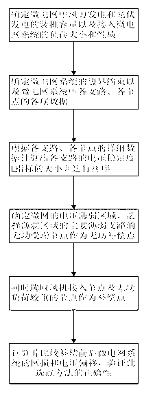
[0038] One, at first, introduce the method flow process of the present invention, specifically include following several steps:

[0039] Step 1, determine the installed capacity of wind power generation and photovoltaic power generation in the microgrid and the load size connected to the microgrid system;

[0040] Step 2. Determine the boundary constraints of the microgrid system and the data of each branch and each node in the microgrid system. The data include: the resistance and reactance of the branch, the active and reactive power flowing into the end node of the branch power; the voltage of the first node of the branch;

[0041] Among them, the boundary constraints include:

[0042] Boundary constraint one: power flow constraint, based on the following formula:

[0043] P i + Σ k = ...


PUM


Abstract

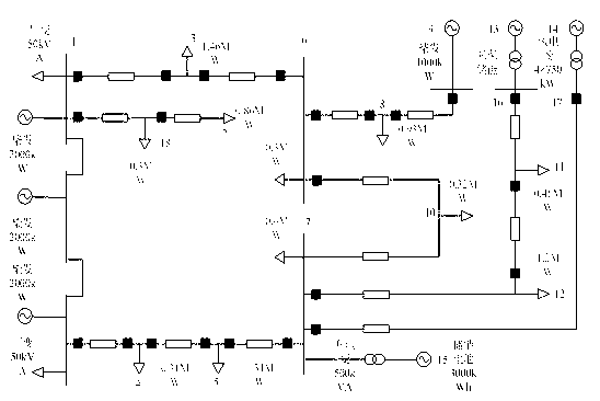
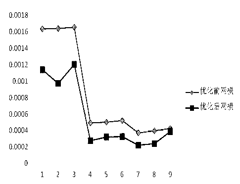
The invention relates to a branch voltage stability analysis based selection method for a reactive power compensation point of a microgrid. The method comprises the steps of determining installed capacities of wind power generation and photovoltaic power generation in the microgrid and the magnitude and the property of a load which is connected with a microgrid system; determining a boundary constraint of the microgrid system and all items of data of all branches and all nodes in the microgrid system; calculating and sequencing voltage stability L indexes of all branches according to detailed data of all branches and all nodes; selecting a reactive power receiving end node of a main weak branch of a weak area as the reactive power compensation point; and calculating and comparing network losses and voltage excursions of the microgrid system before and after compensation, and verifying the correctness of the point selection method. According to the method, the reactive power compensation point in the microgrid can be selected accurately on the basis of the branch voltage stability, the influence of change of the microgrid operation mode and the output volatility of a micro source is low, the method is good in applicability and economy and capable of effectively reducing network losses and voltage excursions of the microgrid.

Description

technical field [0001] The invention relates to a method for selecting a reactive power compensation point, in particular to a method for selecting a reactive power compensation point for a microgrid based on branch circuit voltage stability analysis. Background technique [0002] An important aspect of microgrid reactive power optimal configuration is the selection of microgrid reactive power compensation points. In the reactive power optimization configuration of the microgrid, if all nodes are set as candidate reactive power compensation configuration points, the calculation workload will be greatly increased, and it does not meet the actual needs of the microgrid. Therefore, in the planning and design of the microgrid The appropriate reactive power compensation point should be selected first. The reactive power compensation point has an important impact on the voltage stability and economy of the microgrid operation. If the reactive power compensation point is set unrea...

Claims


Application Information

Patent Timeline
Patent Type & Authority Applications(China)
IPC IPC(8): H02J3/18
CPCY02E10/563Y02E40/30Y02E10/56
Inventor 邓长虹马庆郑训钊何俊黄文涛
Owner WUHAN UNIV
Why Eureka
Eureka Blog
Learn More