
LED (light-emitting diode) driving circuit PCB (printed circuit board)

A LED drive and circuit technology, applied in the electronic field, can solve the problems of limited single-panel area, interlaced wiring, etc., and achieve the effect of optimizing line width and position, less interleaved lines, and stable work

Inactive Publication Date: 2013-07-17
SHANGHAI FOREALIGHT SCI & TECH
View PDF2 Cites 2 Cited by
  • Summary
  • Abstract
  • Description
  • Claims
  • Application Information

AI Technical Summary

Problems solved by technology

The present invention adopts a double-sided PCB substrate, which can selectively arrange part of the circuits on the back of the double-sided PCB substrate, effectively solving the problem that the single-sided PCB area is limited and the wiring is easily staggered

Method used


Image

  • LED (light-emitting diode) driving circuit PCB (printed circuit board)

Examples


Embodiment Construction

[0018] In order to make the technical means, creative features, goals and effects achieved by the present invention easy to understand, the present invention will be further described below in conjunction with specific diagrams.

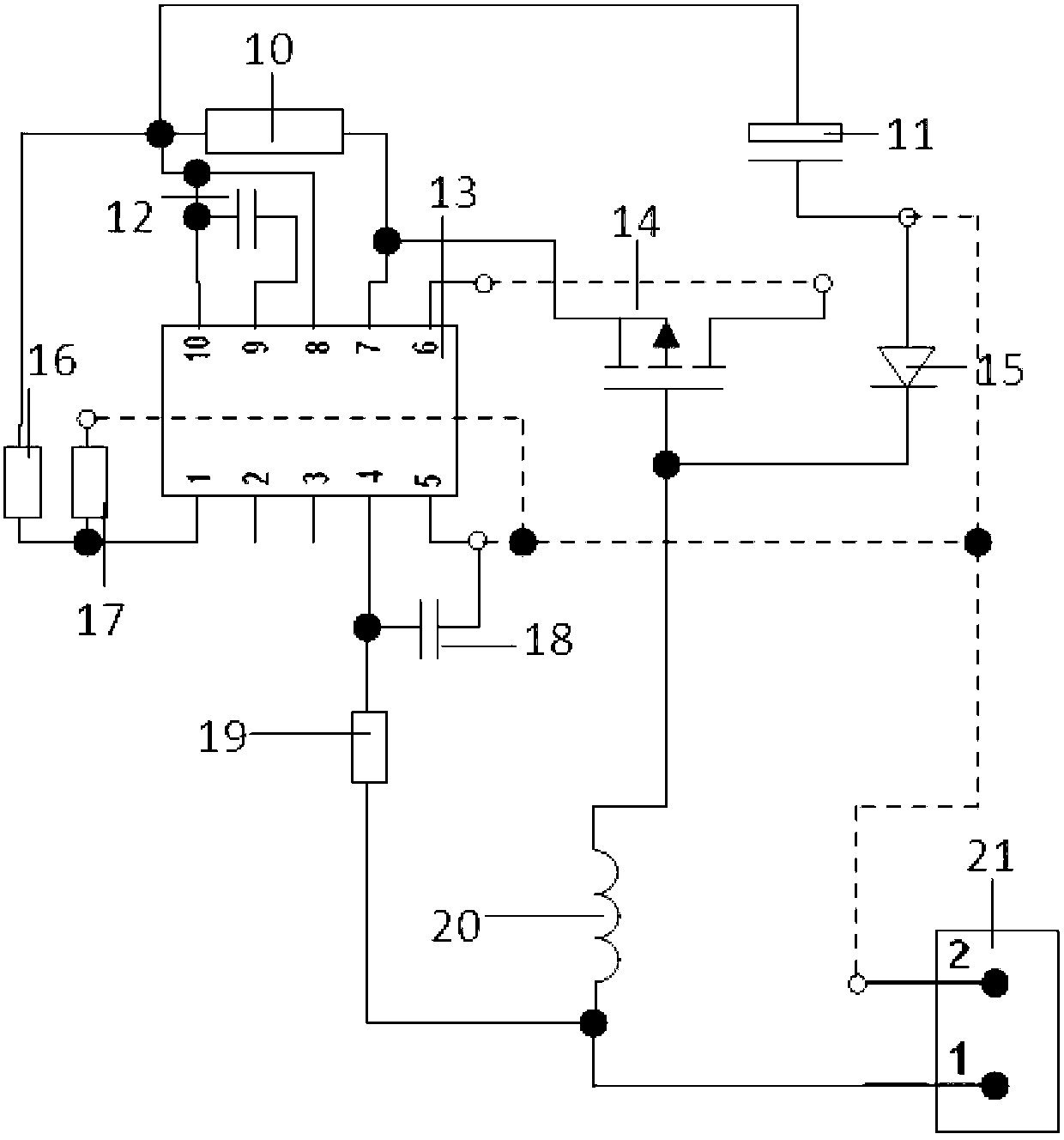
[0019] refer to figure 1 An LED driving circuit PCB includes a PCB substrate, on which wires and electronic components for driving LEDs are arranged, and the PCB substrate is a double-sided PCB substrate.

[0020] The circuit connection relationship between the electronic components in the electronic component group:

[0021] The electronic component group includes a drive control chip 13, a MOS transistor 14, a diode 15, an inductor 20, a first resistor 16, a second resistor 17, a third resistor 19, a fourth resistor 10, a first capacitor 18, a second capacitor 11, The third capacitor 12.

[0022] The first pin of the drive control chip 13 is connected to the first end of the first resistor 16, and the second end of the first resistor 16 is connec...


PUM


Abstract

The invention relates to a circuit PCB (printed circuit board). The LED (light-emitting diode) driving circuit PCB (printed circuit board) comprises a PCB substrate, a wire line for driving an LED to work is arranged on the PCB substrate, and an electronic component group for driving the LED to work is welded to the wire line and comprises a driving control chip. The circuit PCB is characterized in that the PCB substrate is two-sided. The two-sided PCB substrate is adopted by the circuit PCB, part of the line can be selectively distributed on the back of the two-sided PCB substrate, and the problem that a single-sided board is limited in area and wiring staggering occurs easily is solved.

Description

technical field [0001] The invention relates to electronic technology, in particular to a circuit PCB. Background technique [0002] PCB (Printed Circuit Board), the Chinese name is printed circuit board, also known as printed circuit board, printed circuit board, is an important electronic component, a support for electronic components, and a provider of electrical connections for electronic components. [0003] In the design of various types of LED drive circuit PCBs, there are many ways to design the components and circuits of the LED drive circuit. Contents of the invention [0004] The object of the present invention is to optimize the design of the LED driving circuit PCB and provide an LED driving circuit PCB with more stable operation. [0005] The technical problem solved by the present invention can adopt following technical scheme to realize: [0006] An LED driving circuit PCB, comprising a PCB substrate, on which a wire line for driving LEDs is arranged, on ...

Claims


Application Information

Patent Timeline
Patent Type & Authority Applications(China)
IPC IPC(8): H05K1/18H05B37/02
Inventor 林志一张艳李冬鸣
Owner SHANGHAI FOREALIGHT SCI & TECH
Learn More