Energy-harvesting conveyor belts and methods

A technology of conveyors and belts, applied in the direction of conveyors, conveyor objects, conveyor control devices, etc.

Active Publication Date: 2015-06-03
LAITRAM LLC
View PDF6 Cites 0 Cited by
  • Summary
  • Abstract
  • Description
  • Claims
  • Application Information

AI Technical Summary

Problems solved by technology

However, these battery packs require regular monitoring and eventually manual intervention to install new replacements

Method used


Image

  • Energy-harvesting conveyor belts and methods
  • Energy-harvesting conveyor belts and methods
  • Energy-harvesting conveyor belts and methods

Examples


Embodiment Construction

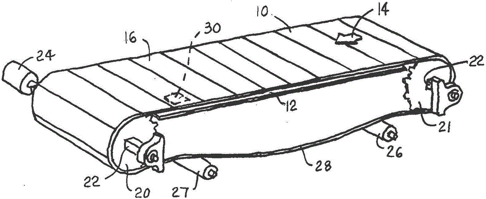
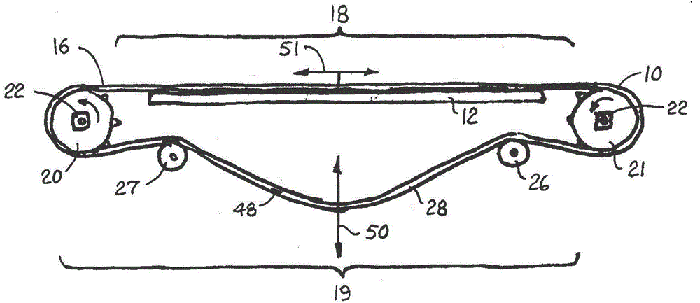
[0022] exist figure 1 and image 3 A version of a conveyor system incorporating features of the present invention is shown in . Conveyor (shown in this example as a conveyor belt 10 supported on a conveying path 12) along a conveying path segment 18 of the endless conveyor path of the belt on an outer conveying surface 16 in a conveying direction 14 on transport items. At the end of the conveyance path, items are conveyed off the conveyor belt. After bypassing the drive sprocket 20 , the conveyor belt 10 passes through a return section 19 on its way around the idler sprocket 21 back to the transport path section 18 . Both the drive sprocket and the idler sprocket are mounted on a rotatable shaft 22 . A drive motor 24 is coupled to the drive shaft in order to drive the belt in the conveying direction 14 . In the return path section 19 the belt is supported between a pair of spaced rollers 26, 27 or shoes so as to absorb sag in the catenary 28 formed between these rollers. ...


PUM


Abstract

Energy-harvesting and -storage devices in conveyor belts and methods for molding those devices integrally into modular belt links and for enhancing energy harvesting through resonance tuning. Piezoelectric materials, electro-active polymers, thermoelectric generators, RF receivers, photovoltaic devices, linear induction generators, and inductive transformer coupling are used to harvest energy to power belt on-board devices.

Description

technical field [0001] The present invention relates generally to motorized conveyors and more particularly to instrumented conveyor belts having on-board devices powered by energy harvested from surrounding sources. Background technique [0002] More often than not, sensors, indicators, transmitters, receivers, and other electrical and electromechanical devices are installed in conveyor belts. Most of these devices require electricity to operate. A separate battery or battery pack, also mounted in the belt, powers these devices. However, these battery packs require regular monitoring and eventually manual intervention to install new replacements. Contents of the invention [0003] This disadvantage is overcome by a conveyor belt embodying features of the present invention. The conveyor belt includes a belt body with an energy harvesting device disposed in or on the belt body. An energy storage device, such as a capacitor or battery, coupled to the energy harvesting de...

Claims


Application Information

Patent Timeline
Patent Type & Authority Patents(China)
IPC IPC(8): B65G15/00
CPCB29D29/06B65G17/08B65G23/00B65G43/00B65G2203/042H02N2/188B65G15/30B65G21/00B29C45/0001B29C45/0005B29C45/1679B29C45/73B29K2105/06B29K2995/0003B29K2995/0005B29K2995/0007B29L2031/7092B65G15/32G01D11/245H02N2/181H02N2/186H02N2/22H02N11/002
Inventor 约瑟夫·M·德帕索
Owner LAITRAM LLC
Why Eureka
Try Eureka