Single-row emergency-stop switch-contact device

A technology of contact device and stop switch, which is applied in the direction of electric switch, contact, contact engagement, etc., can solve problems such as incorrect connection, and achieve the effect of simple and reliable connection

Inactive Publication Date: 2013-07-17
GEORG SCHLEGEL GMBH & CO
View PDF4 Cites 5 Cited by
  • Summary
  • Abstract
  • Description
  • Claims
  • Application Information

AI Technical Summary

Problems solved by technology

This occurs, for example, whenever there is an operationally incorrect connection between the operating device and the electrical contact device

Method used


Image

  • Single-row emergency-stop switch-contact device
  • Single-row emergency-stop switch-contact device
  • Single-row emergency-stop switch-contact device

Examples


Embodiment Construction

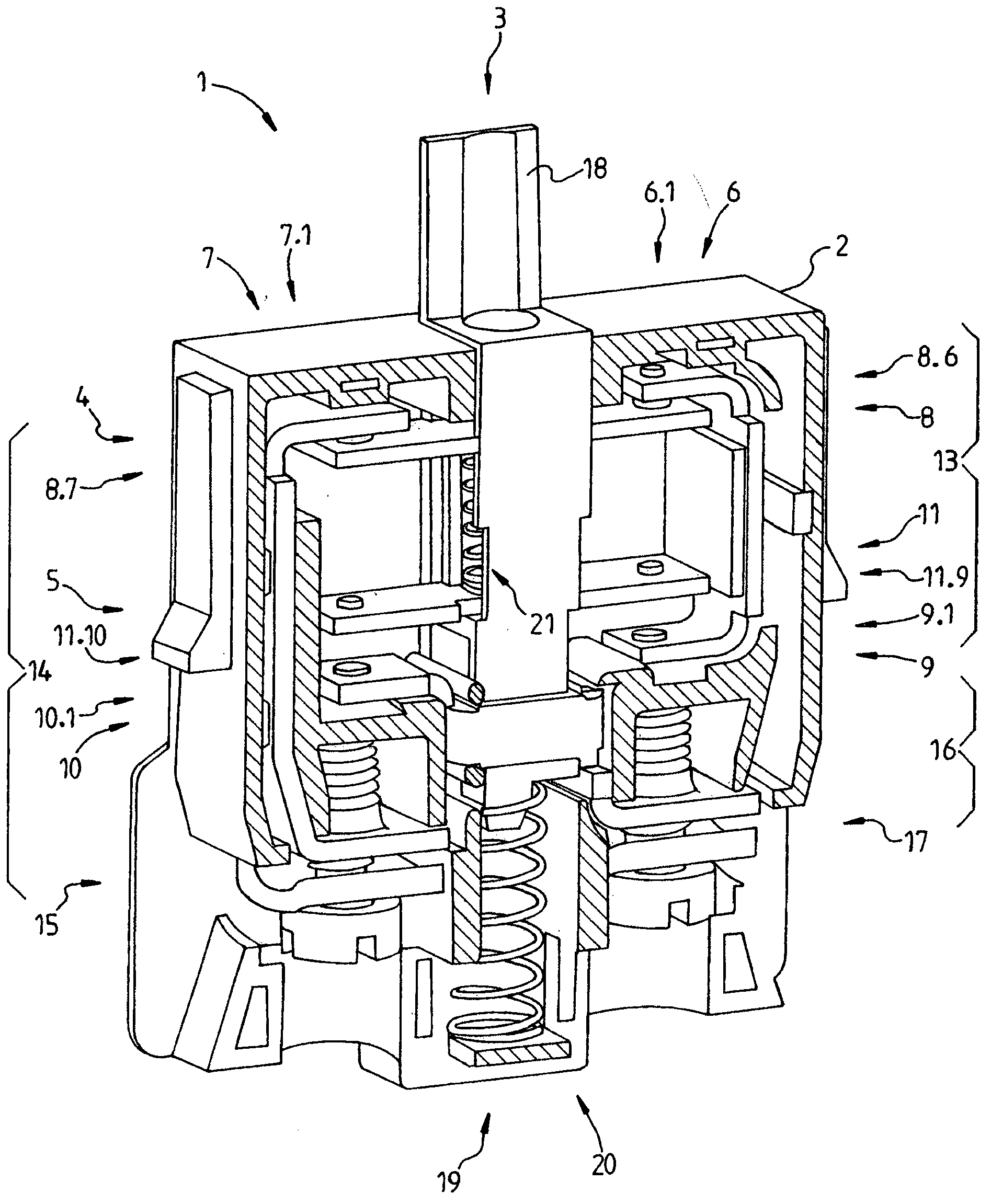
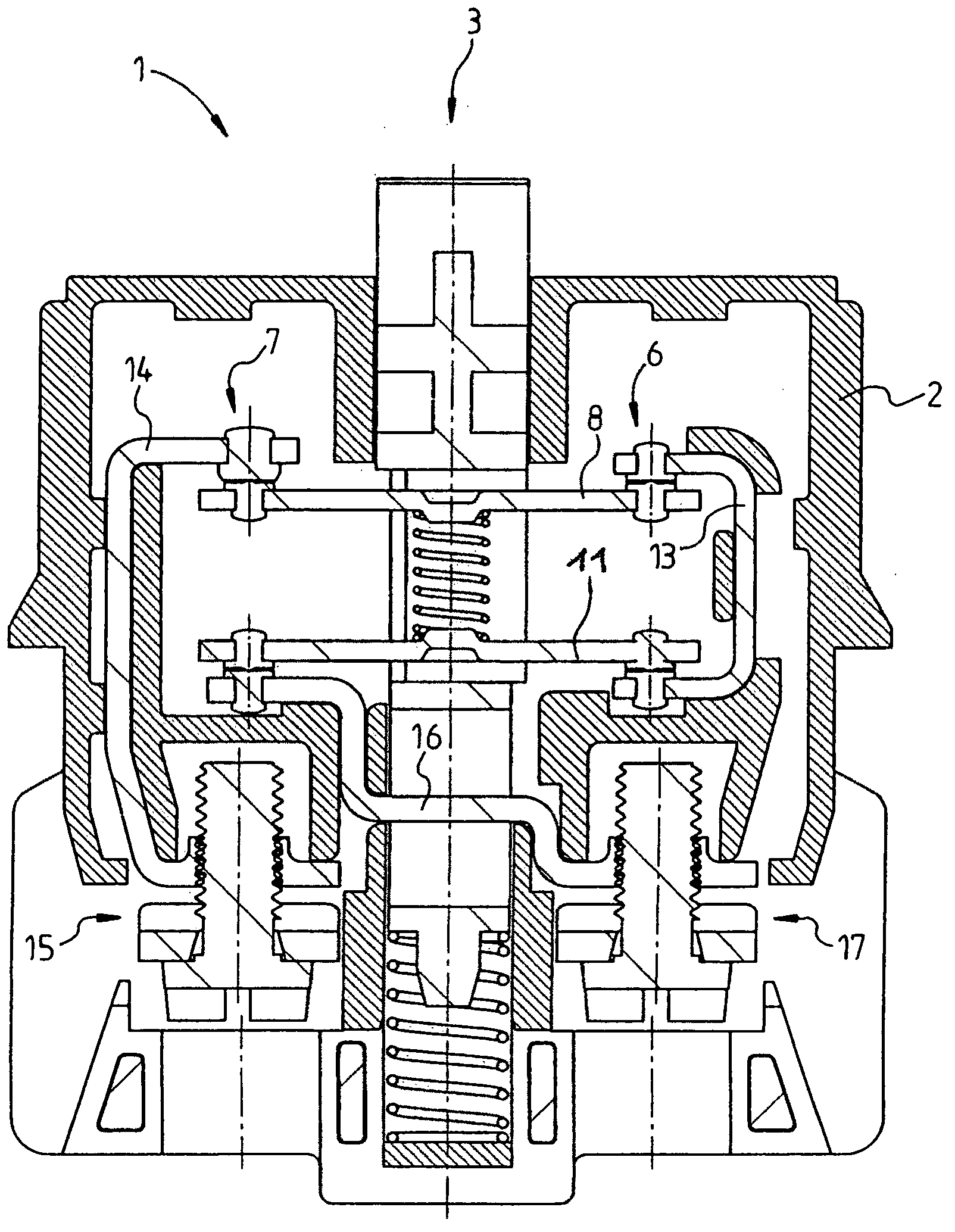
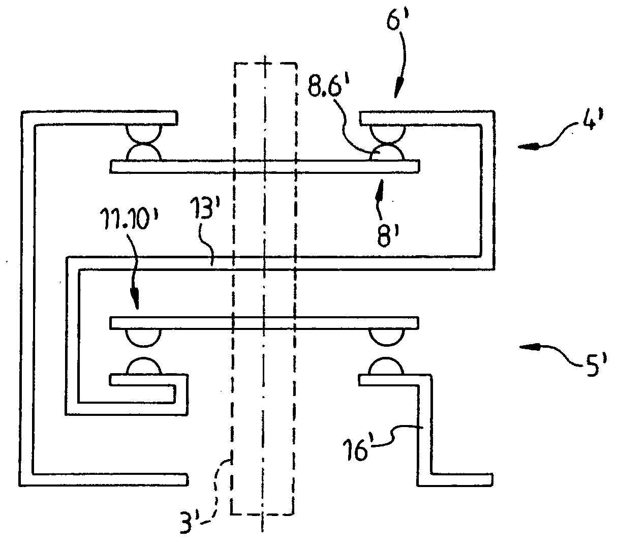
[0033] therefore, figure 1 An electrical contact device 1 is shown with a housing 2 and a push rod 3 movably guided therein. The contact device 1 comprises a first and a second switch contact unit 4, 5, which are each positioned according to the position of the push rod along its axial direction, corresponding to the switch positions specified for the emergency stop switch and explained in detail above, Used to make or break a conductive connection. The first switching contact unit 4 comprises a first contact side 6 , a second contact side 7 and a bridge element 8 which connects the individual contact points 6 . 1 or 7 . 1 . The bridging element can preferably also have contact points 8.6 and 8.7 made of a corresponding contact material. In the state shown, the closed switching contact unit 8 establishes an electrically conductive connection.

[0034] The second switching contact unit 5 comprises in a corresponding manner a first contact side 9 and a second contact side 10 ...


PUM


Abstract

The invention relates to an electrical contact device (1), in particular an emergency stop switch-contact device, comprising a first switch contact unit (4) for creating or disconnecting an electrically conductive connection and a second switch contact unit (5) for creating or disconnecting an electrically conductive connection, wherein a first contact side (6) of the first switch contact unit is connected to a first contact side (9) of the second switch contact unit, and a second contact side (7) of the first switch contact unit is connected to a first connection contact (15) of the contact device and a second contact side (10) of the second switch contact unit is connected to a second connection contact (17) of the contact device, and wherein the two switch contact units are designed to be actuated by a movable push rod (3) acting thereon, characterised in that the two connection contacts are arranged, in relation to the push rod, opposite each other on the contact device and wherein the first and the second switch contact unit are arranged inside a mounting unit (3) that is provided for connection to an actuating device.

Description

technical field [0001] The invention relates to an electrical contact device according to claim 1 and a control device / command device according to claim 16 . Background technique [0002] For safety reasons, emergency stop switches are stipulated for machines and electrical equipment. Such an emergency stop switch is known, for example, from DE 4 101 493 C2 and comprises, on the one hand, an electrical contact device and, on the other hand, an actuating device provided for its actuation. This two-part construction is based on the consideration that the actuating device, also commonly referred to as the manipulator, must be visible and accessible at all times in order to be reliably operable. Only in this way can it be ensured that in the event of a dangerous situation in the machine or plant, it can be disconnected mechanically according to the cut-off operation command provided for this purpose. If such an emergency stop switch is provided for arrangement on a switch cabi...

Claims


Application Information

Patent Timeline
Patent Type & Authority Applications(China)
IPC IPC(8): H01H3/02H01H1/20
CPCH01H1/2025H01H3/022H01H13/503
Inventor E·时力高K·布兰克R·多勒普
Owner GEORG SCHLEGEL GMBH & CO
Why Eureka
Try Eureka