
Patsnap Eureka
For R&D, Patsnap Eureka makes reading and utilizing patents & technical documents easy.
Patsnap Eureka AIR
Designed for self-driven R&D workflows. Generate viable solutions, solve complex R&D challenges, empower your innovation with AI.

Patsnap Eureka Materials
Designed for material experts only. Revolutionize your material R&D, from search, analyze, to developing new materials.

TechResearch
Generate reliable direction feasibility study reports for your R&D in just a few steps.

TechSeek
Discover and master advanced knowledge NOW. Basics, ideas, possibilities, all at once.

TechMind
As an expert in R&D Theories, TechMind can generates customized viable solutions instantly.

TechRisk
Analyze your overall solution with one click, know your potential R&D risks in advance.

TechMonitor
Get weekly tech updates, stay abreast of the latest tech innovations and key insights.
Hip joint prosthesis
A technology of hip joint prosthesis and femoral stem, which is applied in the field of hip joint prosthesis, can solve the problems of increasing the risk of acetabular dislocation, easily causing large trochanteric fractures, affecting the blood supply of the medullary cavity, and achieving enhanced initial stability and anti-rotation Performance, prevention of greater trochanteric fractures, and the effect of facilitating implantation into the medullary cavity
- Summary
- Abstract
- Description
- Claims
- Application Information
AI Technical Summary
Problems solved by technology
Method used
Image

Examples
Embodiment Construction
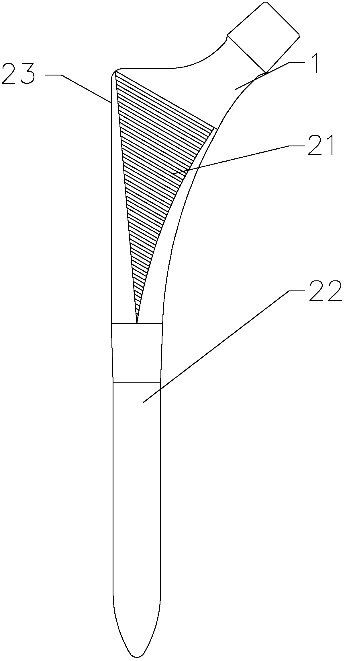
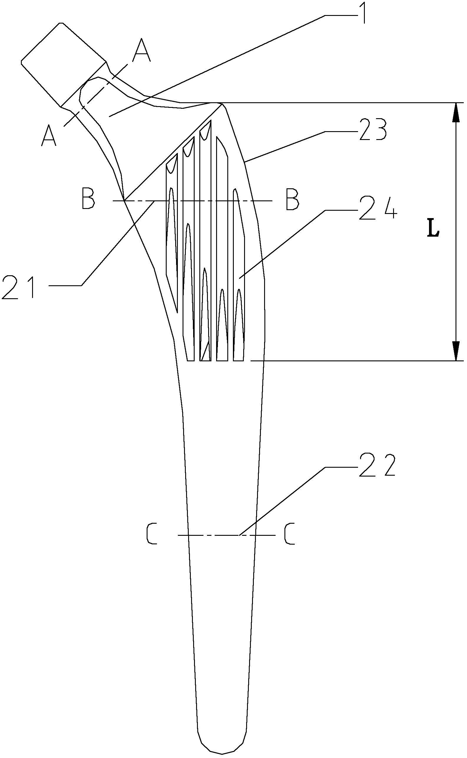
[0025] see figure 2 As shown, the hip joint prosthesis of the present invention includes a femoral neck 1 and a femoral stem, wherein the femoral stem includes a proximal end 21 and a distal end 22, and the present invention adds a longitudinal crest 24 on the proximal end 21 of the femoral stem.
[0026] Preferably, five longitudinal crests 24 can be arranged on the proximal end 21 of the femoral stem of the present invention, and the length L of each longitudinal crest is preferably 50mm, which is in line with the Chinese femoral anatomical characteristics, and the fixation effect is the best. If it is too short, the fixation effect of the proximal femur will be poor. If it is too long, the longitudinal crest will easily reach the cortical bone of the femur, making implantation difficult, and there is a risk of femoral fracture and fracture. The human proximal femur has a lot of cancellous bone in the medullary cavity, and the longitudinal crest can be inserted into the can...
PUM
| Property | Measurement | Unit |
|---|---|---|
| Arc radius | aaaaa | aaaaa |
| Long trail | aaaaa | aaaaa |
| Short diameter | aaaaa | aaaaa |
Abstract
Description
Claims
Application Information
 - R&D Engineer
- R&D Manager
- IP Professional
- Industry Leading Data Capabilities
- Powerful AI technology
- Patent DNA Extraction
Browse by: Latest US Patents, China's latest patents, Technical Efficacy Thesaurus, Application Domain, Technology Topic, Popular Technical Reports.
© 2024 PatSnap. All rights reserved.Legal|Privacy policy|Modern Slavery Act Transparency Statement|Sitemap|About US| Contact US: help@patsnap.com