Forced-discharging and self-cleaning type centrifugal throwing machine
What is Al technical title?
Al technical title is built by PatSnap Al team. It summarizes the technical point description of the patent document.
A technology of self-cleaning and drying machines, applied in centrifuges, centrifuges with rotating drums, etc., can solve problems such as blockage of filter holes, achieve the requirements of free from lubrication, convenient installation, and lower installation accuracy Effect
Inactive Publication Date: 2013-07-24
CHINA UNIV OF PETROLEUM (EAST CHINA)
View PDF4 Cites 9 Cited by
Summary
Abstract
Description
Claims
Application Information
AI Technical Summary
This helps you quickly interpret patents by identifying the three key elements:
Problems solved by technology
Method used
Benefits of technology
Problems solved by technology
[0003] The purpose of the present invention is to solve the problem of automatic cleaning of blockages in filter holes and optimize Transmission structure, optimized feeding and discharging structure, improved installation and replacement of filter cartridges, and reduced sealing points to simplify maintenance procedures and meet the needs of drying drilling cuttings in oilfields
Method used
Image
Click on the blue label to locate the original text in one second.
Reading with bidirectional positioning of images and text.
Examples
Embodiment Construction
[0028] Below with reference to accompanying drawing, further describe:
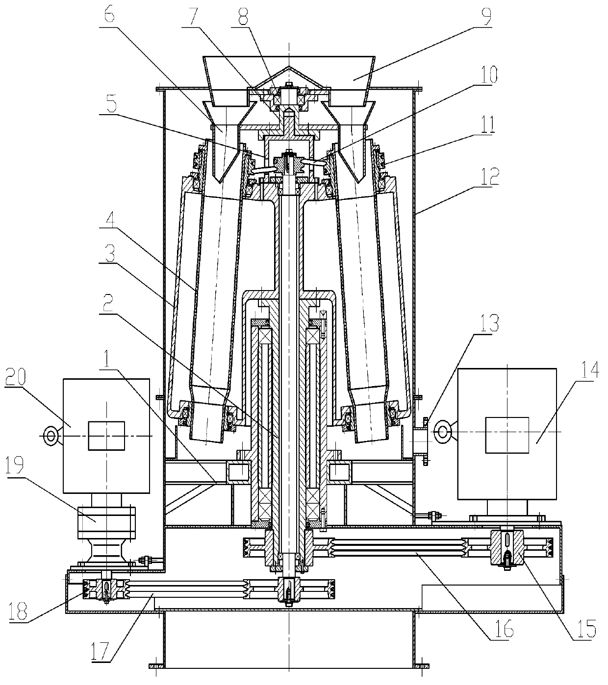
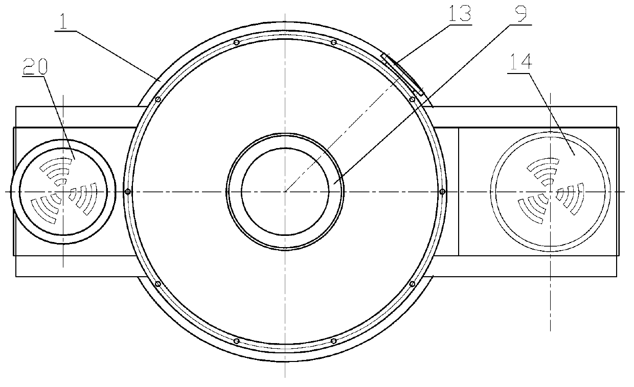
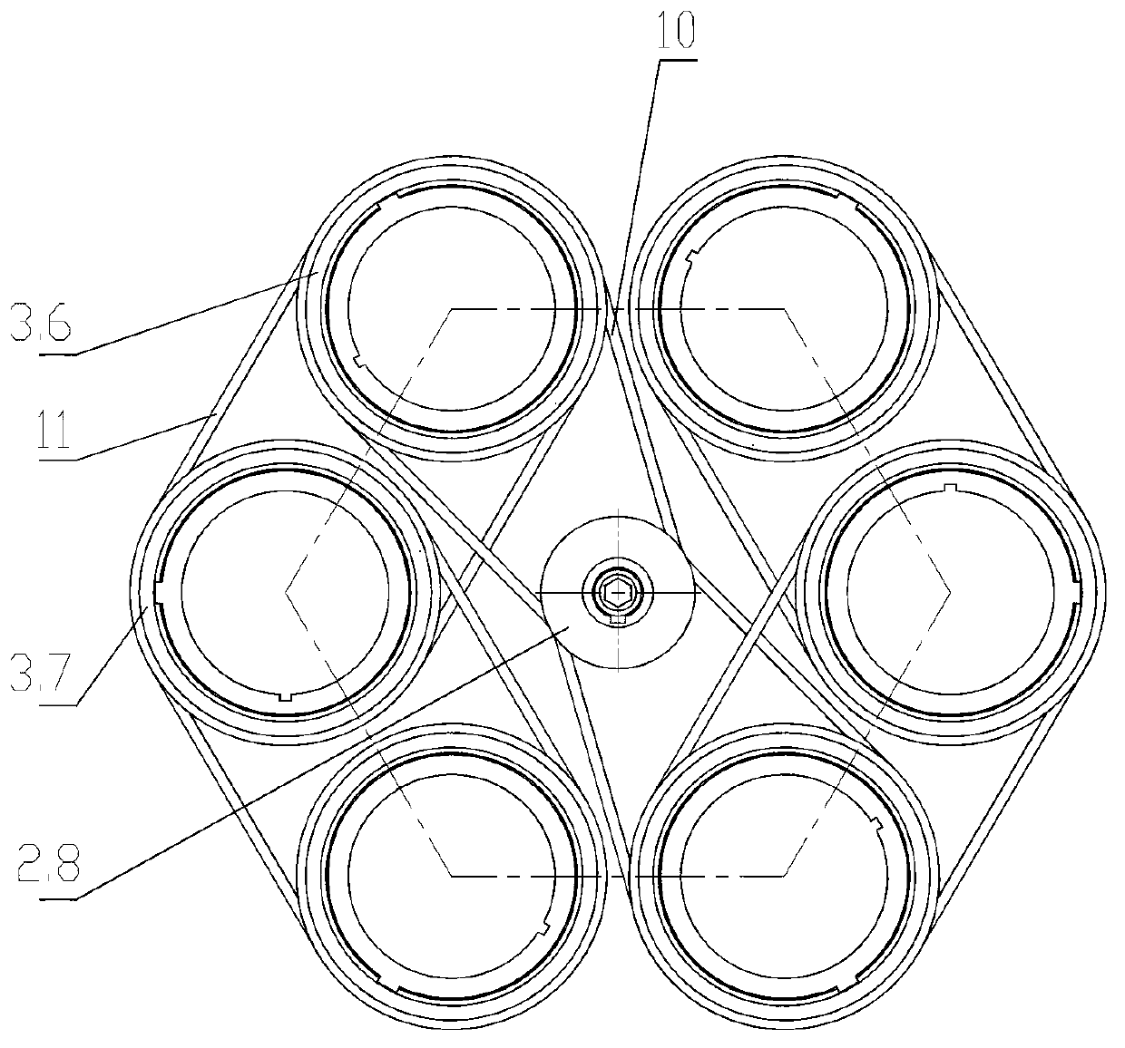
[0029] According to the present invention, if Figure 1 to Figure 12 As shown, 1 is the skirt seat, 2 is the transmission assembly, 3 is the drum assembly, 4 is the filter cartridge, 5 is the connecting shaft, 6 is the dynamic feeding port, 7 is the end shaft, 8 is the auxiliary bearing, 9 is the static 10 is the linkage transmission belt, 11 is the transmission belt between cylinders, 12 is the shell, 13 is the discharge pipe, 14 is the revolution motor, 15 is the revolution main pulley, 16 is the revolution transmission belt, 17 is the rotation transmission Belt, 18 is the rotation main belt pulley, 19 is the speed reducer, 20 is the rotation motor, 3.6 is the filter cartridge pulley, 3.7 is the adjacent filter cartridge pulley, and 2.8 is the linkage pulley.
[0030] Such as Figure 1 to Figure 12In the self-cleaning centrifugal dryer shown, the lower end of the housing 12 is connected to the upper e...
PUM
Abstract
The invention relates to a forced-discharging and self-cleaning type centrifugal throwing machine. The centrifugal throwing machine is characterized by comprising a skirt seat, a transmission assembly, rotary drum assemblies, filter cylinders, a connecting shaft, movable material inlets, an end shaft, an auxiliary bearing, a stationary material inlet, coupling transmission pulleys, a transmission pulley between cylinders, a casing, a liquid outlet, a revolution motor and a rotation motor, wherein each rotary drum assembly consists of a rotary drum main body, an upper filter cylinder seat, a lower filter cylinder seat, an upper seat bearing, a lower seat bearing and a filter cylinder belt wheel, each upper filter cylinder seat and each lower filter cylinder seat are respectively arranged in holes formed in each rotary drum main body by each upper seat bearing and each lower seat bearing, the upper end of each upper filter cylinder seat is provided with each filter cylinder belt wheel, the upper end of each rotary drum main body is uniformly provided with six to ten upper filter cylinder seat holes, the lower end of each rotary drum main body is uniformly provided with corresponding lower filter cylinder seat holes, the corresponding lower filter cylinder seat holes and the upper filter cylinder seat holes are arranged in a coaxial way, and an included angle of 3 to 9 degrees is formed between the axis and the axis of the holes in each rotary drum main body. The centrifugal throwing machine has the advantages that the problem of automatically cleaning articles blocked in the holes is solved; the number of sealing points is reduced, so the maintenance and operation procedures are simplified; and the requirement of throwing drill chips of oilfield drilling wells is met.
Description
Technical field: [0001] The invention relates to a forced unloading and self-cleaning centrifugal drying machine, in particular to a multi-tube filtering centrifugal drying machine used for drying drilling cuttings in oil fields. Background technique: [0002] There are two main types of centrifugal dryers commonly used, one is that the filter cartridge rotates with the drum, and the other is that the drum rotates while the filter cartridge is stationary. At present, the cuttings dryer commonly used in oilfield drilling has a main structure. is to adopt the latter. There are two obvious disadvantages in the oilfield drilling cuttings drying machine currently used: (1) Since the drum rotates at a high speed, the cuttings are directly thrown to the filter cartridge due to the centrifugal force when the drum is fed, and the cuttings are directly thrown to the filter cartridge. The impact force of the net is very large, and the filter cartridge and the drum are severely worn, w...
Claims
Application Information
Patent Timeline
Application Date:The date an application was filed.
Publication Date:The date a patent or application was officially published.
First Publication Date:The earliest publication date of a patent with the same application number.
Issue Date:Publication date of the patent grant document.
PCT Entry Date:The Entry date of PCT National Phase.
Estimated Expiry Date:The statutory expiry date of a patent right according to the Patent Law, and it is the longest term of protection that the patent right can achieve without the termination of the patent right due to other reasons(Term extension factor has been taken into account ).
Invalid Date:Actual expiry date is based on effective date or publication date of legal transaction data of invalid patent.