
A hand-held glue injection booster device

A force-boosting device and hand-held technology, which is applied to devices and coatings that apply liquid to surfaces, and can solve problems such as safety accidents, limited operating space, and small air gap volume.

Active Publication Date: 2015-10-28
BEIJING UNIV OF CHEM TECH
View PDF5 Cites 0 Cited by
  • Summary
  • Abstract
  • Description
  • Claims
  • Application Information

AI Technical Summary

Problems solved by technology

However, due to the limited operating space, small air gap volume, and extremely viscous glue, manual operation is required during injection, which is extremely inefficient and requires a lot of force. Excessive force can easily cause the needle of the syringe to come out, which not only makes the glue Liquid spraying pollutes the operating environment and is more likely to cause safety accidents
[0003] The glue guns on the market usually require special injection syringes, and the glue solution is stored in the glue barrel in advance and sold as a whole. However, there are no ready-made glue barrels on the market for the glue solution used in special occasions, and it needs to be extracted immediately with a medical syringe; traditional glue The front end of the gun push rod is directly connected to the piston, and pushed into the syringe containing the glue. This design has a long overall length of the glue gun, which is not suitable for use in a narrow space; at the same time, the traditional glue gun is only used for applying glue, not for injection. , does not use needles and has no associated needle fixation device, not suitable for air gap filling of sandwich materials

Method used


Image

  • A hand-held glue injection booster device
  • A hand-held glue injection booster device
  • A hand-held glue injection booster device

Examples


Embodiment Construction

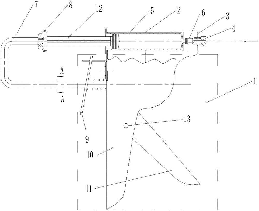
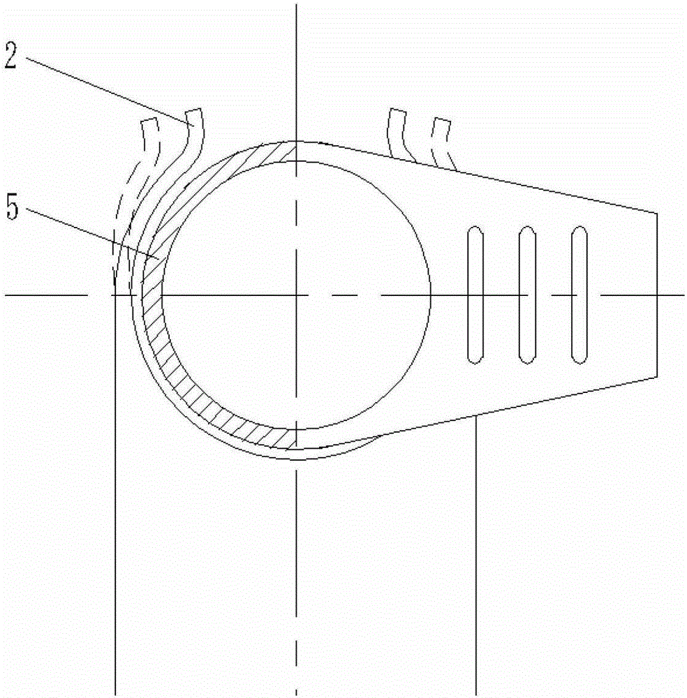
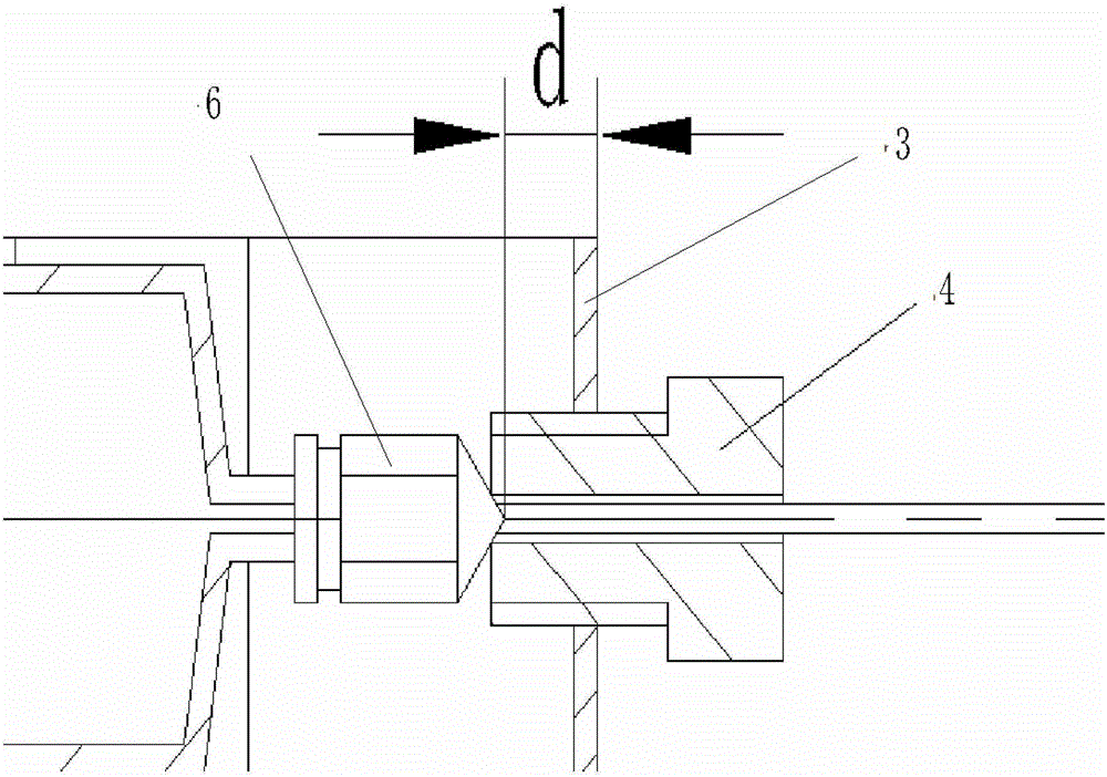
[0020] A kind of hand-held glue injection booster device of the present invention, as figure 1 As shown, the device mainly includes: booster mechanism 1, syringe bracket 2, baffle plate 3, thread ferrule 4, syringe 5, needle head 6, push rod 7, push piece 8, and thread ferrule 4 is the booster The power mechanism 1 adopts a traditional glass glue gun power-increasing mechanism, including a grip 10 and a trigger 11 connected with a pin 13, and an iron sheet 9 for unloading pressure. The syringe support 2 is located above the booster mechanism 1, and is made as a whole with the booster mechanism 1, such as figure 2 As shown, the syringe support 2 is a circular groove with an elastic closure on the top; the baffle 3 is located at the front end of the syringe support 2, and the two are welded together. There is a hole in the middle of the threaded ferrule 4, which is connected with the baffle 3 are screwed together, such as image 3 As shown; the syringe 5 is located inside the...


PUM


Abstract

The invention relates to a handheld glue solution injection reinforcing device. The handheld glue solution injection reinforcing device mainly comprises a reinforcing mechanism, a needle cylinder support, a baffle plate, a thread clamping sleeve, a needle cylinder, a needle head, a push rod and a pushing piece, wherein a traditional glass glue gun reinforcing mechanism is used as the reinforcing mechanism, the baffle plate is arranged at the front end of the needle cylinder support, the baffle plate and the needle cylinder support are welded together, a hole is formed in the middle of the thread clamping sleeve, and the thread clamping sleeve and the baffle plate are connected together through a thread; the needle cylinder is positioned in the needle cylinder support, the injection end of the needle cylinder is connected with the needle head, the needle head passes through the hole of the thread clamping sleeve, the push rod is a U-shaped rod, one end of the push rod is inserted the reinforcing mechanism of a glue gun, the other end of the push rod is connected with a piston through the pushing piece, and the section of the push rod is of an oblateness the two sides of which are scabbled; and a wafer with a round groove is used as the pushing piece, the pushing piece and the push rod are fixed through the thread, and a round head at the end part of the piston of the needle cylinder after compacting contacts the bottom of the groove of the pushing piece and is clamped in the groove. According to the handheld glue solution injection reinforcing device provided by the invention, a common medical needle cylinder containing glue solution and the glass glue gun are utilized as a reinforcing structure, the handheld glue solution injection reinforcing device is easily available, beneficial to recovery, energy-saving and environment-friendly.

Description

technical field [0001] The invention relates to a hand-held glue injection device, which is especially suitable for filling air gaps of glue in interlayer materials in special positions such as limited operating space. Background technique [0002] In industrial production, sandwich materials are widely used, which have the advantages of light weight and high structural strength. In order to ensure the stability of the performance and related characteristics of the interlayer material, it is necessary to ensure that there are no defects such as air gaps between the interlayers. In order to eliminate the air gap defect, the usual practice is to find out the defect location, and use a medical syringe to inject glue to fill the air gap between the interlayer materials. However, due to limited operating space, small air gap volume, and extremely viscous glue, manual operation is required during injection, which is extremely inefficient and requires a lot of force. Excessive for...

Claims


Application Information

Patent Timeline
Patent Type & Authority Patents(China)
IPC IPC(8): B05C17/10
CPCY02P70/38Y02P70/10
Inventor 安瑛李月林宋乐丁玉梅杨卫民
Owner BEIJING UNIV OF CHEM TECH
Learn More