Supercharge Your Innovation With Domain-Expert AI Agents!

Concrete core slab extruding device

An extrusion device and hollow slab technology, which is applied in the field of concrete hollow slab preparation devices, can solve the problems of wasting manpower and low production efficiency, and achieve the effect of improving quality

Inactive Publication Date: 2013-07-24
南京环力重工机械有限公司
View PDF0 Cites 0 Cited by
  • Summary
  • Abstract
  • Description
  • Claims
  • Application Information

AI Technical Summary

Problems solved by technology

[0002] The current concrete hollow slabs all use templates and are prepared manually, which has low production efficiency and wastes manpower

Method used


Image

  • Concrete core slab extruding device
  • Concrete core slab extruding device
  • Concrete core slab extruding device

Examples


Embodiment 1

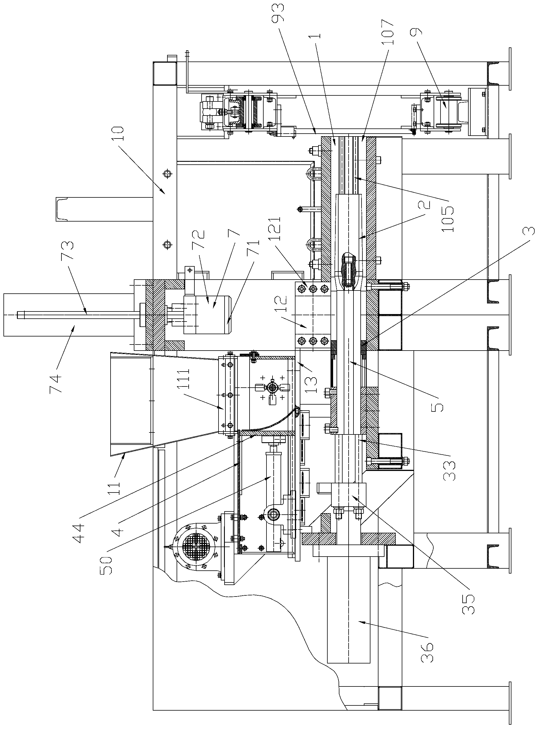
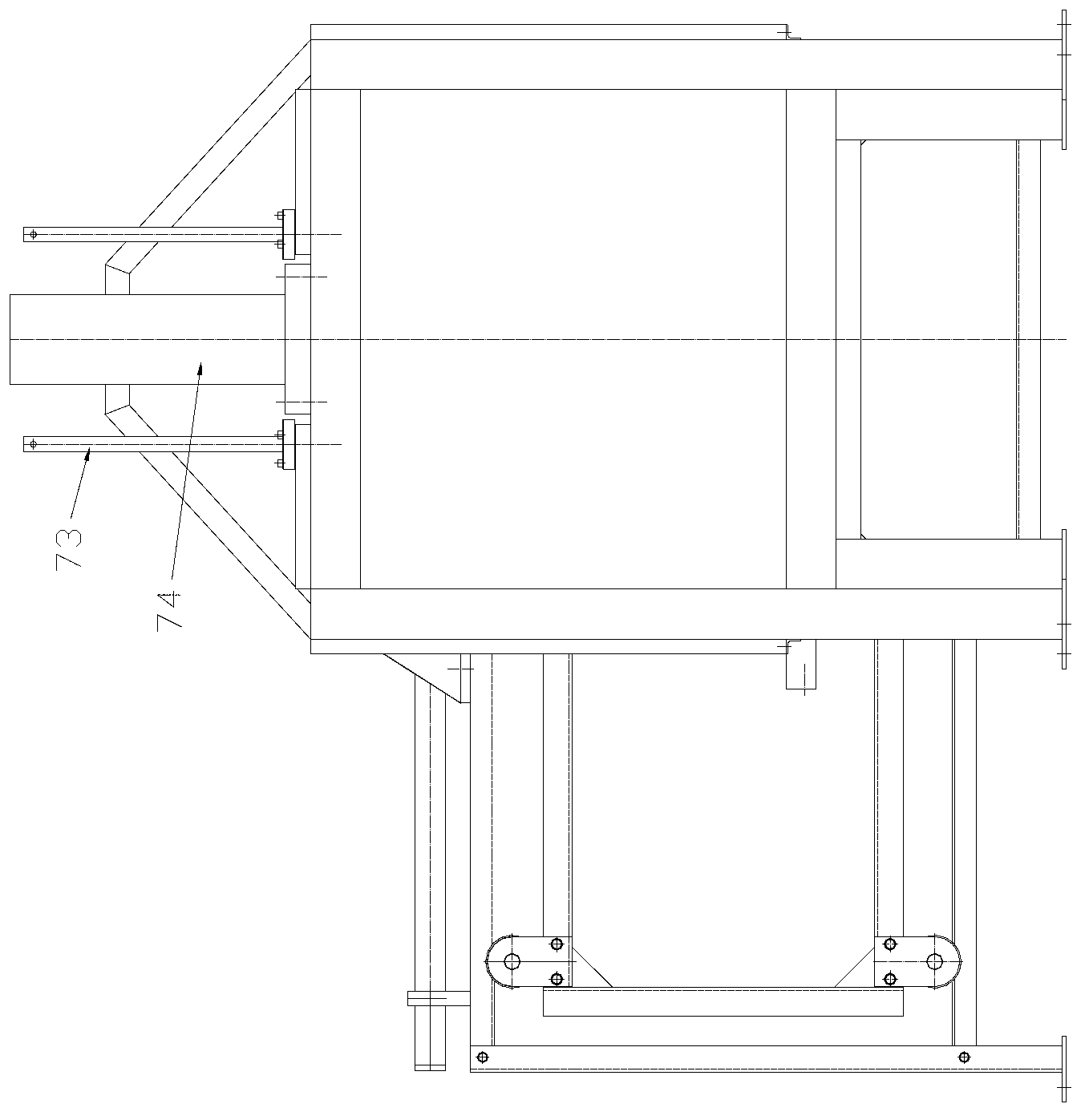
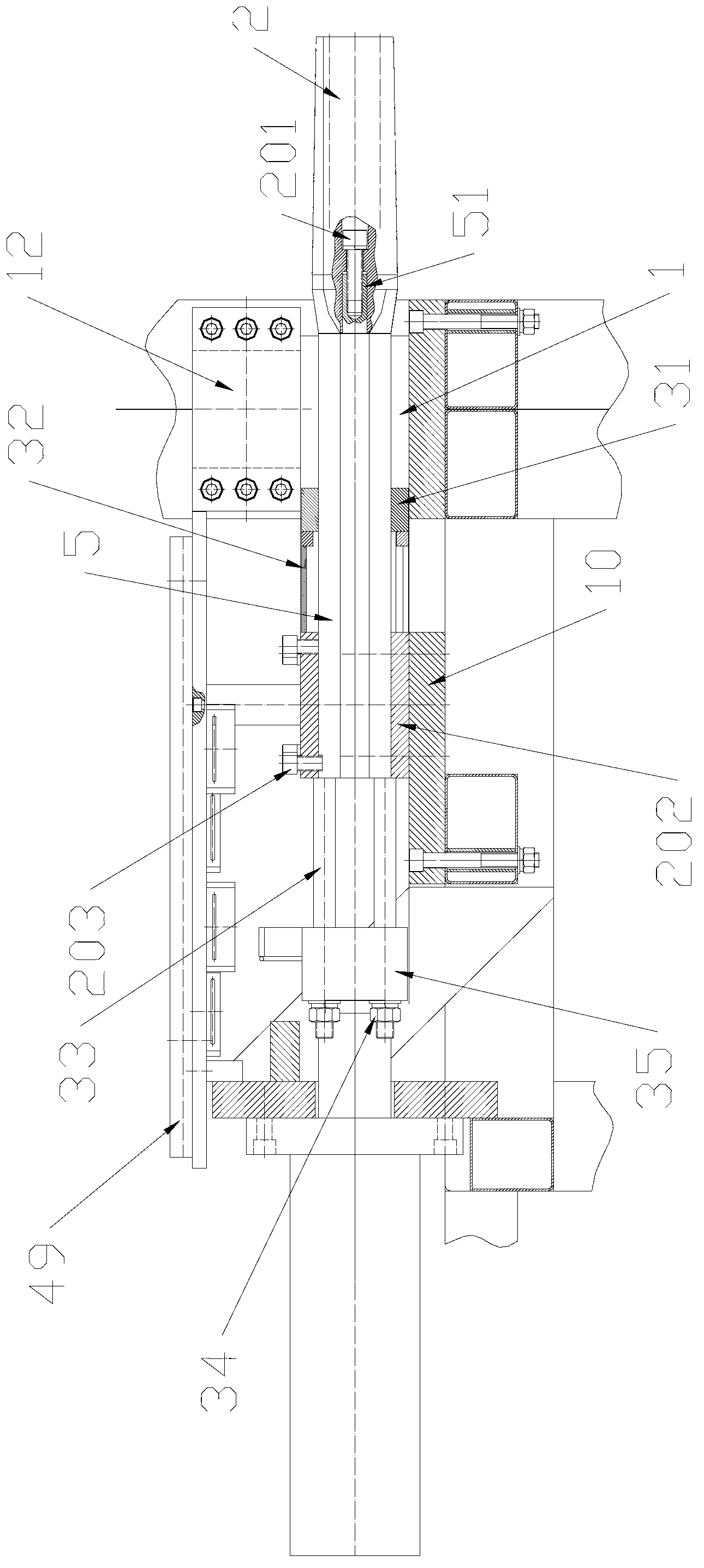
[0052] see figure 1 , 2 The concrete hollow slab extrusion device shown includes an extrusion bin 1, a mold core 2, a push plate device 3, a moving feeder device 4, a knife holder rod 5, a compression molding device 7, a wire cutting device 9, a frame 10, Hopper 11, feed bin 12, shielding plate 13.

[0053] The extrusion chamber 1 is a cuboid surrounded by four extrusion chamber plates 101 , the left end is an inlet 106 , and the right end is an outlet 107 . On the inner walls of the two opposing extruded bins 101, a side convex formwork 102 and a side concave formwork 103 are arranged. The side convex template 102 is provided with two parallel protrusions 104 extending to the exit of the extrusion bin, and the side concave template 103 is provided with two parallel concave portions 105 extending to the exit of the extrusion bin. The raised portion 104 is a corresponding tongue and groove structure.

[0054] The compression molding device 7 includes a compression molding l...

Embodiment 2

[0078] Embodiment 2 is different from Embodiment 1 in that: the mold core is different, and the connection structure between the mold core and the knife holder rod is different. Specific instructions are given below.

[0079] In Embodiment 2, the right ends of the eight knife rest bars 5 are respectively connected to the left ends of the upper and lower three connecting plates 14, and there are 33 mold cores 8 (the mold cores on both sides of the middle horizontal plane are half mold cores, the One half of the mold core is connected with another horizontally adjacent mold core. Two half mold cores can be counted as a complete mold core), distributed on three horizontal planes, and two adjacent mold cores located on one horizontal plane The distance between the mold cores is equal, and the mold cores at different levels are staggered up and down. From the left end to the right end, the outer circumference of the cross-section of the mold core 8 gradually increases within the sco...


PUM


Abstract

The invention provides a concrete cored slab extruding device, which can be used for continuously preparing concrete cored slabs and has high production efficiency. The extruding device comprises a frame, and an extruding cabin with a feeding hole, wherein a feeding hole cover plate is connected with a driving device of the feeding hole cover plate; one end of each die core in the extruding cabin is connected with a tool rest rod on the frame; the periphery of each die core increases gradually from one end to the other end, keeps constant, and then reduces gradually; a push plate which is arranged on the tool rest rod in a sliding way is connected a push plate pushing device; the sum of the area of the maximum transverse section of each die core is x, the sum of the area of one end of each die core is y, the sum of the other end of each die core is z, and the area of the transverse section of the extruding cabin is w, so that (w-y) is less than or equal to 3.5(w-x) and is more than or equal to 2.5(w-x), and (w-z) is less than (w-x) and is more than (w-y); the discharging hole of a bin is communicated with the feeding hole; the feeding hole cover plate passes through the bin while moving; the periphery of the feeding hole cover plate is matched with the inner wall of the bin; when a movable trolley device is moved to a certain position, the outlet of a stirring cabin is communicated with the inlet of the bin; and when the movable trolley device is moved to another position, the outlet of the stirring cabin is enclosed by using a shielding plate.

Description

technical field [0001] The technology relates to a preparation device for concrete hollow slabs, in particular to a continuous preparation device for concrete hollow slabs. Background technique [0002] Present concrete hollow slabs all adopt formwork, are prepared by manual method, and production efficiency is low, wastes manpower. Contents of the invention [0003] The purpose of this technology is to provide a concrete hollow slab extrusion device capable of continuously preparing concrete hollow slabs and having high production efficiency. [0004] The concrete hollow slab extrusion device includes a frame, and one end fixed on the frame is an extrusion bin whose inlet is the other end is an outlet; Cover plate; the feed port cover plate is connected with the feed port cover plate driving device arranged on the frame to drive the feed port cover plate to move; at least one mold core is arranged in the extrusion chamber, and one end of the mold core is connected to the...

Claims


Application Information

Patent Timeline
Patent Type & Authority Applications(China)
IPC IPC(8): B28B3/20
Inventor 许朝阳
Owner 南京环力重工机械有限公司
Features
  • R&D
  • Intellectual Property
  • Life Sciences
  • Materials
  • Tech Scout
  • Unparalleled Data Quality
  • Higher Quality Content
  • 60% Fewer Hallucinations
Learn More