Mechanical-damping-type yarn tensioner without skimming wear

A technology of mechanical damping and tensioner, which is applied in looms, textiles, textiles, and papermaking, etc. It can solve the problems of complex structure, hairiness, and large bending curvature of the tensioner, and achieve practical and reliable adjustment methods, simple adjustment methods, and flexible bending. The effect of small curvature

Inactive Publication Date: 2013-07-24
窦其勇
View PDF0 Cites 4 Cited by
  • Summary
  • Abstract
  • Description
  • Claims
  • Application Information

AI Technical Summary

Problems solved by technology

[0002] The existing tensioners used in the production of glass fiber and rock fiber cloth usually refer to the ordinary tensioner structure for adjusting the tension of civil textiles such as cotton yarn and chemical fiber, or directly use ordinary tensioners. The common characteristics of these tensioners are: The tension is provided by the sliding friction of the yarn relative to the parts on the tensioner. Since the diameter of the parts that provide sliding friction is small, the bending radius of the yarn is small so that the bending curvature is large; this structure of the tensioner is suitable for large twist and soft texture. It is completely suitable for civil textile yarns, but for glass fibers and rock fibers with small twist, hard texture, fear of bending and friction, sliding friction and bending with large curvature will seriously damage the yarn, reducing Reduced yarn strength, resulting in more hairiness, affecting production efficiency and product quality;
[0003] Currently, hysteresis damping tensioners are usually used in the production of glass fiber electronic fabrics with particularly high quality requirements in the existing technology. This kind of tensioner has complex structure, high price and high energy consumption. Unbearable in fiber cloth production

Method used


Image

  • Mechanical-damping-type yarn tensioner without skimming wear
  • Mechanical-damping-type yarn tensioner without skimming wear
  • Mechanical-damping-type yarn tensioner without skimming wear

Examples


Embodiment Construction

[0016] Describe the present invention in detail below in conjunction with accompanying drawing:

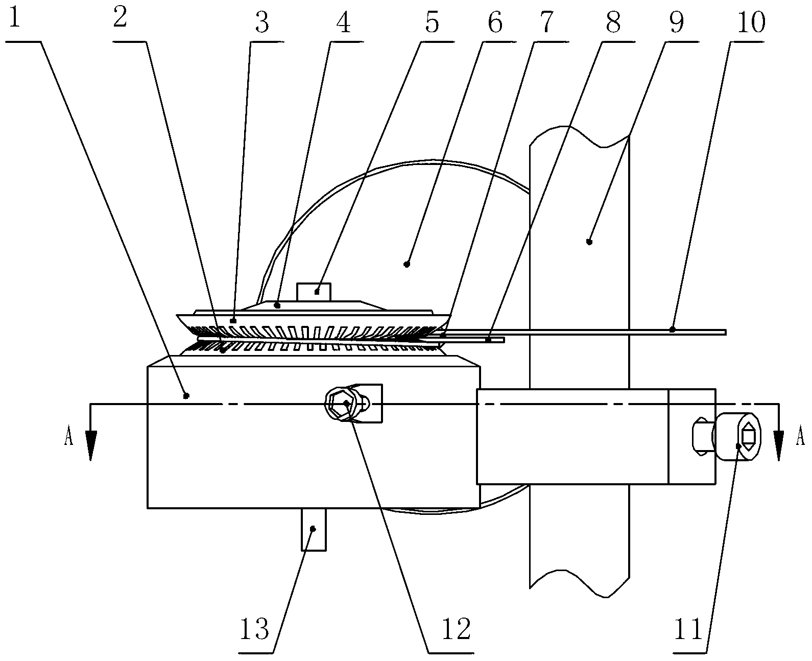
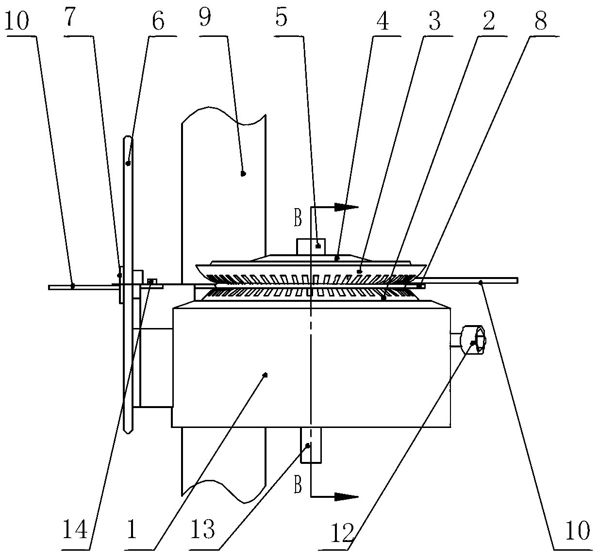
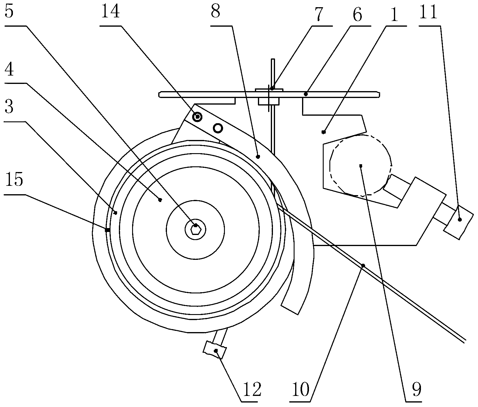
[0017] This kind of tensioner comprises the lower tension disc 2 of the prior art, the upper tension disc 3, the tension disc pressing plate 4, the pressing plate fixing screw 5, the yarn dividing sheet 8, the yarn retaining plate 6, and the porcelain eye 7; Figure 1-6 As shown, the characteristics of this tensioner are: the lower tension disc 2 and the upper tension disc 3 are arranged on the shoulder of the rotor 13 through the center hole, and the tension disc pressing plate 4 is arranged on the top of the upper tension disc 3, and the tension disc pressing plate 4 passes through The pressure plate fixing screw 5 fixes the lower tension disc 2 and the upper tension disc 3 on the rotor 13; a cylinder is arranged under the shoulder of the rotor 13, and an annular hole is arranged in the cylinder, and the central axis of the annular hole is the rotor shaft; the tensioner The seat...


PUM


Abstract

The invention relates to a mechanical-damping-type yarn tensioner without skimming wear. The tensioner is characterized in that a pair of large-diameter tension plates is used, and tension adjustment is achieved through the facts that a flaky spring is pushed and pressed towards a rotor through a tension adjustment screw, the rotor is rubbed to produce damping force, the damping force is adjusted through adjustment of push force of the tension adjustment screw, the damping force is transferred to yarns through the tension plates due to the fact that the pair of the large-diameter tension plates and the rotor are fixedly assembled together, and accordingly the yarn tension adjustment is achieved. Due to the pure mechanical type adjustment mode, relative sliding between the yarns and parts providing the damping force does not exist, the yarn bending radius is large, the yarn bending curvature is small, and the yarn tensioner is suitable for glass fiber and rock fiber which are not bending-resistant and friction-resistant, simple, practical, reliable, high in quality and low in price.

Description

technical field [0001] The invention relates to a tensioner for yarn tension adjustment, in particular to a mechanical damping yarn non-sliding wear tensioner suitable for tension adjustment of glass fiber and rock fiber yarn. Background technique [0002] The existing tensioners used in the production of glass fiber and rock fiber cloth usually refer to the ordinary tensioner structure for adjusting the tension of civil textiles such as cotton yarn and chemical fiber, or directly use ordinary tensioners. The common characteristics of these tensioners are: The tension is provided by the sliding friction of the yarn relative to the parts on the tensioner. Since the diameter of the parts that provide sliding friction is small, the bending radius of the yarn is small so that the bending curvature is large; this structure of the tensioner is suitable for large twist and soft texture. It is completely suitable for civil textile yarns, but for glass fibers and rock fibers with sma...

Claims


Application Information

Patent Timeline
Patent Type & Authority Applications(China)
IPC IPC(8): D03D47/34
Inventor 窦其勇
Owner 窦其勇
Why Eureka
Try Eureka