Tool for repairing oil-water well inward concave sleeve

A technology for oil and water wells and casings, which is applied to wellbore/well components, earth-moving drilling, etc., can solve the problems of cumbersome operation process, time-consuming and labor-intensive, etc., and achieve the effect of convenient operation process, improved repair quality, and smooth repair.

Active Publication Date: 2013-07-24
CHENGDU ZHIRONG ZHICHUANG INTPROP MANAGEMENT CO LTD
View PDF7 Cites 0 Cited by
  • Summary
  • Abstract
  • Description
  • Claims
  • Application Information

AI Technical Summary

Problems solved by technology

[0003] The purpose of the present invention is to solve the problem of cumbersome, time-consuming and labor-intensive operation when repairing concave deformed casings in oil-water wells, and to provide a tool for repairing concave casings in oil-water wells that is easy to implement and easy to operate

Method used


Image

  • Tool for repairing oil-water well inward concave sleeve
  • Tool for repairing oil-water well inward concave sleeve

Examples


Embodiment 1

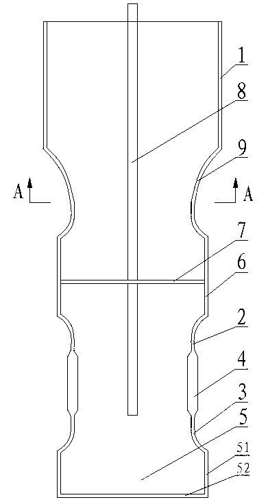
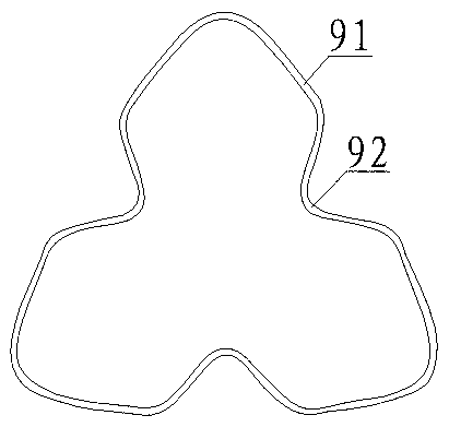
[0020] Such as figure 1 and figure 2 As shown, the tooling used to repair the concave casing in the oil and water well includes the main pipe 1, the first expansion section, the positioning pipe 6, the second expansion section and the head 5 connected sequentially from top to bottom. The main pipe 1 has a slightly inner diameter It is smaller than the inner diameter of the casing and ensures that there is no friction when the main pipe 1 is embedded in the casing. The main pipe 1, the first expansion section, the positioning pipe 6, the second expansion section and the sealing head 5 integrally constitute a pipe body with an open upper end and a sealed lower end. The first expansion section is the third expansion tube 9. The third expansion tube 9 is preferably made of rubber. The side wall of the third expansion tube 9 is formed by annular splicing of a plurality of convex arc walls 91 and a plurality of concave arc walls 92 , Wherein any one of the plurality of outer convex...

Embodiment 2

[0023] The main difference between this embodiment and embodiment 1 is that this embodiment further restricts the structure of the head 5 in embodiment 1: the head 5 of this embodiment includes a guide tube 51 and a lower sealing plate 52, and the lower sealing The plate 52 closes the opening at the lower end of the guide tube 51, and the second expansion tube 3 of the second expansion section is connected to the head 5 by being connected to the guide tube 51. Among them, the guide tube 51 and the lower sealing plate 52 are preferably made of stainless steel. In order to facilitate the placement of the second expansion section in the concave and deformed part of the casing, the inner diameter of the guide tube 51 is smaller than the inner diameter of the main pipe 1, and the inner diameter of the connecting tube 4 is smaller than the inner diameter of the guide tube 51; in order to facilitate placing the first expansion section in the casing In the concave deformed part, the in...


PUM


Abstract

The invention discloses a tool for repairing an oil-water well inward concave sleeve. The tool comprises a main pipe (1), a first expansion section, a locating pipe (6), a second expansion section and a seal head (5), wherein the main pipe (1), the first expansion section, the locating pipe (6), the second expansion section and the seal head (5) are successively connected from top to bottom, the first expansion section is a third expansion pipe (9), and the side wall of the third expansion pipe (9) is formed by a plurality of outward protruded arc walls (91) and a plurality of inward concave arc walls (92) in an annular split joint mode. The second expansion section comprises a first expansion pipe (2), a connection pipe (4) and a second expansion pipe (3), wherein the first expansion pipe (2), the connection pipe (4) and the second expansion pipe (3) are successively connected from top to bottom. The tool utilizing the structure is simple in integral structure and convenient to implement. When the tool is applied, the inward concave deformed part of the sleeve is primarily repaired through the second expansion section, the inward concave deformed part of the sleeve is secondarily repaired through the first expansion section, operation is convenient and rapid, time and labor are saved, and smoothness of the inner wall of the sleeve is guaranteed after repairing.

Description

technical field [0001] The invention relates to a maintenance machine in the field of oil exploitation, in particular to a tool for repairing the inner concave casing of an oil-water well. Background technique [0002] Oil and water well casings often have concave deformation due to crustal movement or improper operation. The concave and deformed casing prevents oil extraction equipment from entering the well, which will affect the normal production of oil and water wells, and may even cause oil and water wells to stop production. In order to improve the utilization rate of oil-water wells and increase oil production, it is particularly important to repair the concave deformation of the casing. However, the oil-water well has a certain depth, and it is difficult to repair the concave deformation of the casing. The operation process is cumbersome, time-consuming and labor-intensive, and the cost is high. Contents of the invention [0003] The purpose of the present inven...

Claims


Application Information

Patent Timeline
Patent Type & Authority Applications(China)
IPC IPC(8): E21B29/10
Inventor 贺昶明
Owner CHENGDU ZHIRONG ZHICHUANG INTPROP MANAGEMENT CO LTD
Why Eureka
Try Eureka