Supersonic combustion method actuated by combination plasma

A supersonic combustion and plasma technology, which is applied in combustion engines, combustion air/combustion-air treatment, internal combustion piston engines, etc., can solve the problems of large flow loss, low supersonic combustion performance, and large cavity size, etc., and achieve ignition delay Short time, low ignition energy, and improved efficiency

Inactive Publication Date: 2013-07-24
HARBIN INST OF TECH
View PDF4 Cites 11 Cited by
  • Summary
  • Abstract
  • Description
  • Claims
  • Application Information

AI Technical Summary

Problems solved by technology

[0004] The purpose of the present invention is to solve the problems of large cavity size, large flow loss and low supersonic combustion performance in the existing concave cavity combustion method, and propose a supersonic combustion method under combined plasma excitation

Method used


Image

  • Supersonic combustion method actuated by combination plasma
  • Supersonic combustion method actuated by combination plasma
  • Supersonic combustion method actuated by combination plasma

Examples


specific Embodiment approach 1

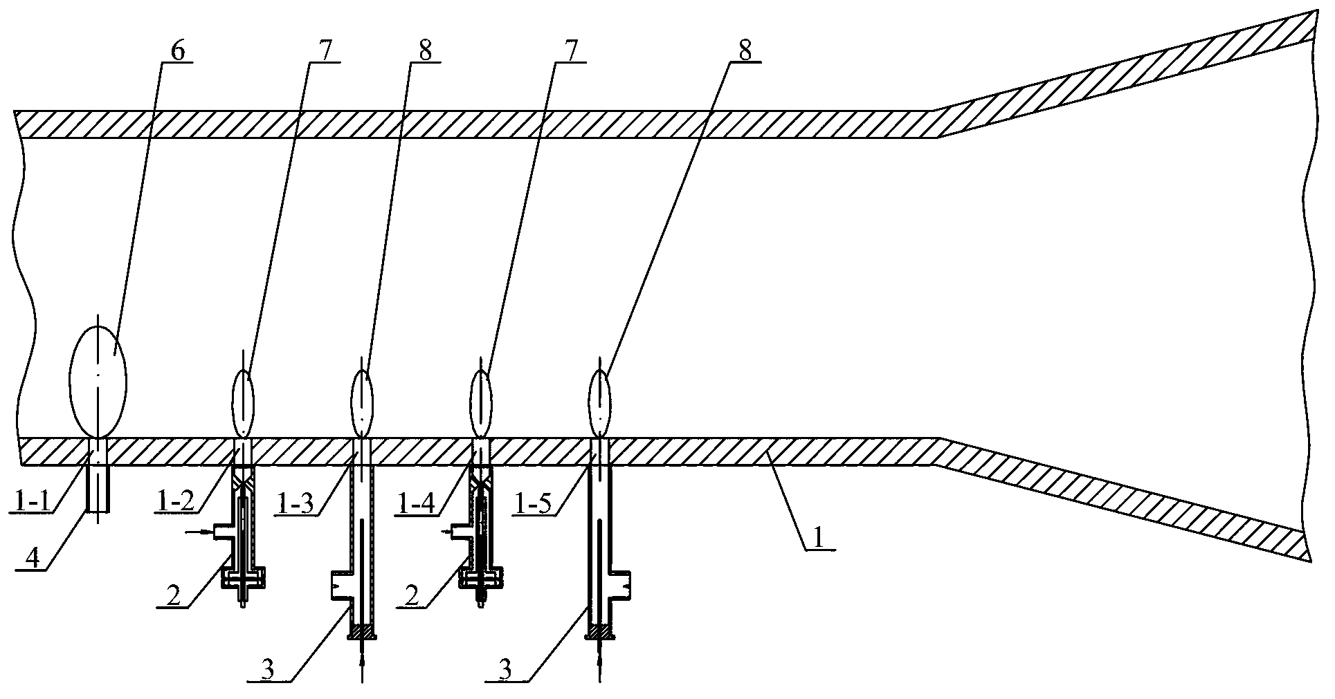
[0013] Embodiment 1: Combining Figure 1 to Figure 3 Describe this implementation mode, this implementation mode is realized through the following steps:

[0014] Step 1: Process the first through hole 1-1, the second through hole 1-2, the third through hole 1-3, the fourth through hole 1-4 and the The fifth through hole 1-5, the inner surface of the first through hole 1-1, the second through hole 1-2, the third through hole 1-3, the fourth through hole 1-4 and the fifth through hole 1-5 Both are coated with ceramic film;

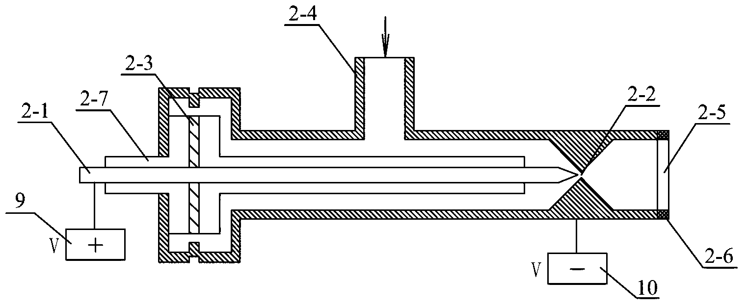
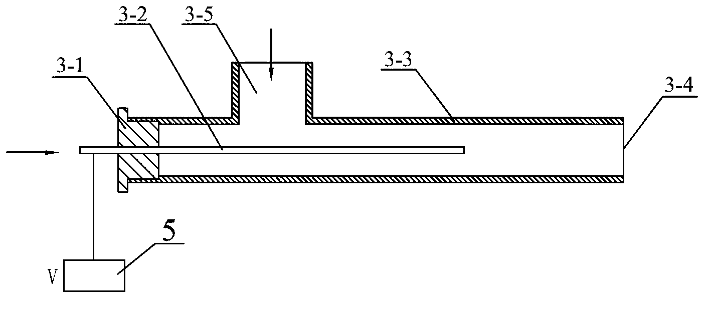
[0015] Step 2, the input end of the first through hole 1-1 is connected with the fuel output pipe 4, the input ends of the second through hole 1-2 and the fourth through hole 1-4 are respectively connected with the outlet on the heat balance plasma generator 2, The input ends of the third through hole 1-3 and the fifth through hole 1-5 are respectively connected with the outlet on the non-thermal equilibrium plasma generator 3;

[0016] Step 3, the fuel ...

specific Embodiment approach 2

[0019] Specific implementation mode 2: Combining figure 1 Describe this embodiment, this embodiment is the first through hole 1-1, the second through hole 1-2, the third through hole 1-3, the fourth through hole 1-4 and the fifth through hole 1 in step 1 -5 has a thickness of the ceramic film on the inner surface of 0.1 mm to 0.2 mm. The ceramic film realizes the insulating effect between the plasma and the wall surface, and the ceramic film can generate secondary electron emission under the collision of the plasma, which is beneficial to the stable propagation of the plasma in the through hole. Other steps are the same as in the first embodiment.

specific Embodiment approach 3

[0020] Specific implementation three: combination figure 1 Describe this embodiment, this embodiment is the first through hole 1-1, the second through hole 1-2, the third through hole 1-3, the fourth through hole 1-4 and the fifth through hole 1 in step 1 The thickness of the ceramic film on the inner surface of -5 is 0.15 mm. Other steps are the same as in the second embodiment.


PUM


Abstract

The invention discloses a supersonic combustion method actuated by combination plasma, relates to the supersonic combustion method for an engine combustion chamber, and solves the problems that by using an existing concave chamber type combustion method, the concave chamber dimensions are large, the flow loss is large, and the supersonic combustion performance is poor. The method comprises the steps that 1) a ceramic membrane is plated on the inner surface of each through hole; 2) the first through hole is connected with a fuel oil outlet pipe, the second through hole and the fourth through hole are connected with a thermal equilibrium plasma generator respectively, and the third through hole and the fifth through hole are connected with a non-thermal equilibrium plasma generator respectively; 3) fuel oil is injected into the combustion chamber through the first through hole; 4) a working medium is ejected from the thermal equilibrium plasma generator, is injected into a combustion area of the engine combustion chamber and ignites the fuel oil at the combustion area to form diffusion flame and realize ignition; and 5) jet cooling plasma is ejected from the non-thermal equilibrium plasma generator, and is injected into different positions of the combustion chamber through the third through hole and the fifth through hole for forming reliable combustion. The method provided by the invention is used for organizing supersonic combustion.

Description

technical field [0001] The invention relates to a supersonic combustion method in an engine combustion chamber, in particular to a supersonic combustion method under combined plasma excitation. Background technique [0002] In the supersonic combustion technology, the incoming flow flows at supersonic speed in the combustion chamber, and the stagnation time is only a few milliseconds. It is very difficult to realize the ignition and combustion of fuel in such a short time. [0003] The concave cavity combustion method is currently the most commonly used supersonic combustion tissue method. The fuel is introduced into the combustion chamber through the pipeline upstream of the concave cavity, and the fuel is diffused in the low-speed vortex area in the concave cavity to realize combustion in the high-speed airflow. In order to stabilize the flame, the size of the concave cavity is required to be large to construct its large-scale low-speed vortex area, so that the combustibl...

Claims


Application Information

Patent Timeline
Patent Type & Authority Applications(China)
IPC IPC(8): F02B51/04F02M27/04
CPCY02T10/12
Inventor 唐井峰徐敏李楠于达仁
Owner HARBIN INST OF TECH
Why Eureka
Try Eureka