
Bevel gear universal reducer

A universal reducer, bevel gear technology, applied in the direction of gear transmission, belt/chain/gear, coupling, etc., can solve the problem of increasing the weight, volume and cost of the mechanical system, the processing technology and reliability need to be improved, The problems of complex connection between the shafts of the mechanical system, etc., achieve the effects of simple structure, convenient manufacturing and processing, and reasonable support

Active Publication Date: 2015-06-24
TONGJI UNIV
View PDF8 Cites 0 Cited by
  • Summary
  • Abstract
  • Description
  • Claims
  • Application Information

AI Technical Summary

Problems solved by technology

If the intersecting angle of the two shafts is constantly changing, a special universal joint is required in series to realize the universal transmission, which often complicates the connection relationship between the shafts of the mechanical system, and each independent transmission part including the universal joint requires Independent sealing and lubrication system increases the weight, volume and cost of the mechanical system
[0003] Patent CN2191317 mentions a universal reducer using the principle of double bevel gears, but the processing methods of each component are complicated and lack reasonable space support, so the processing technology and reliability need to be improved

Method used


Image

  • Bevel gear universal reducer

Examples


Embodiment Construction

[0012] The present invention will be further described below in conjunction with the accompanying drawings.

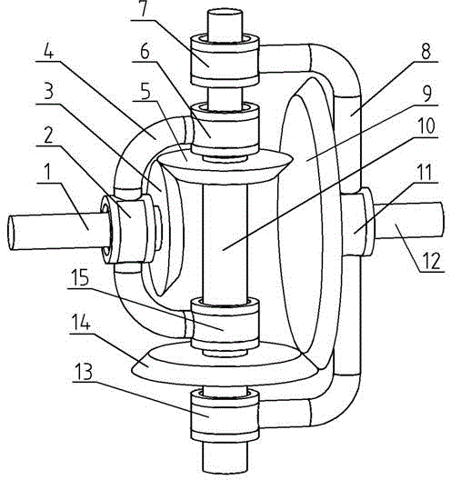
[0013] see figure 1 shown. The present invention consists of a driving shaft 1, a first rotating hinge 2, a driving shaft bevel gear 3, a driving shaft fork 4, an intermediate shaft first bevel gear 5, a second rotating hinge 6, a fifth rotating hinge 7, a driven shaft fork 8, The driven shaft bevel gear 9, the intermediate shaft 10, the fourth rotating hinge 11, the driven shaft 12, the sixth rotating hinge 13, the second bevel gear 14 of the intermediate shaft, and the third rotating hinge 15.

[0014] figure 1 Among them, the driving shaft 1 and the driven shaft 12 are respectively the power input shaft and the power output shaft of the whole mechanism, and the axes of the two shafts are located on the same plane. The driving shaft 1 is hinged with the driving shaft fork 4 through the first rotating hinge 2, so the driving shaft fork 4 can rotate relatively aro...


PUM


Abstract

The invention discloses a bevel gear universal reducer which comprises a driving shaft bevel gear, a middle shaft first bevel gear, a middle shaft second bevel gear, a driven shaft bevel gear, a driving shaft fork, a driven shaft fork, a driving shaft, a middle shaft, a driven shaft and a plurality of rotating hinges. The driving shaft and the driven shaft are perpendicular to the middle shaft in a coplanar mode, and the driving shaft is crossed with the driven shaft in a coplanar mode. The driving shaft is hinged with the driving shaft fork through a rotating hinge, and the driven shaft is hinged with the driven shaft fork through a rotating hinge. The middle shaft is respectively hinged with the driving shaft fork and the driven shaft fork on the same axis through four rotating hinges. The two pairs of bevel gears are respectively used for transmitting motive power. The bevel gear universal reducer breaks the limitation that an existing reducer only can achieve transmission conversion between two crossed shafts with fixed relative positions, the reducer has adaptivity to change of a crossed axis angle, a universal transmission mechanism does not need to be additionally arranged, reduction or reverse speed-up transmission can be conducted on two random crossed shafts, changing within a certain range, of the crossed axis angle, structure is simple, and operation is reliable.

Description

technical field [0001] The invention relates to a new type of transmission mechanism, in particular to a new type of transmission mechanism with universal speed reduction function proposed by using the structural principle of bevel gears. Background technique [0002] The reducer is a commonly used mechanical transmission mechanism with many different forms and types. However, the existing reducers can only realize reduction transmission between two shafts whose relative positions are fixed. For example, the commonly used cylindrical gear reducer is generally used for the reduction transmission between two parallel shafts; the ordinary bevel gear is mostly used for the reduction transmission between two intersecting shafts with a certain space angle. Among the existing reducer products, the same reducer is generally only suitable for the reduction transmission of a specific shaft angle. If the intersecting angle of the two shafts is constantly changing, a special universal...

Claims


Application Information

Patent Timeline
Patent Type & Authority Patents(China)
IPC IPC(8): F16H1/20F16D3/16
Inventor 陈辛波张擎宇唐峰王弦弦王威
Owner TONGJI UNIV
Learn More