Method for measuring ground impedance of large grounding grid

A technology of grounding impedance and measurement method, applied in the direction of grounding resistance measurement, etc., can solve the problem of large shunt ratio of lightning conductor

Active Publication Date: 2013-07-24
ELECTRIC POWER RES INST OF GUANGDONG POWER GRID +1
View PDF5 Cites 26 Cited by
  • Summary
  • Abstract
  • Description
  • Claims
  • Application Information

AI Technical Summary

Problems solved by technology

However, in the actual measurement, it is found that the shunt ratio of the lightning protection line may be very large, which is much larger than the previously imagined value. The measurement practice of the grounding imp

Method used


Image

  • Method for measuring ground impedance of large grounding grid
  • Method for measuring ground impedance of large grounding grid
  • Method for measuring ground impedance of large grounding grid

Examples


Embodiment 1

[0069] A method for measuring the grounding impedance of a large-scale grounding grid in a substation, the method includes the following steps:

[0070] (1) Use the current-voltage method of measuring the grounding impedance of the large-scale grounding grid in the prior art for wiring. According to the site terrain and soil uniformity, choose the compensation method or the distance method in the prior art, and apply and step on the large-scale grounding grid. (2) Different frequency test current of the same frequency;

[0071] (2) Inject a 6A, 53Hz test current at any position of the large grounding grid, and the wireless frequency selection communication instrument at the measurement point samples the waveform of the 53Hz test current in real time, and the amplitude and phase of the test current can be obtained from the waveform The phase information of the waveform phase of the 53Hz test current is wirelessly transmitted to the field area of ​​the large grounding grid, and ...

Embodiment 2

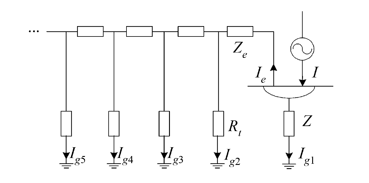
[0098] After the grounding grid of a 110kV substation is expanded, the equivalent diagonal length of the entire grounding grid is D≈360m. During the test, a 110kV overhead line has entered the substation. A lightning conductor and an OPGW optical fiber ground wire have been introduced into the 110kV outlet frame in the station and connected to the main grounding network. The 10kV cable line has not yet been erected and entered the substation.

[0099] Choose the reverse method, apply the different frequency current to measure the grounding impedance of the main grounding grid, and the result is 0.191Ω. Because the lightning conductor and the OPGW optical fiber ground wire shunt the test current outward, the ground impedance measurement result is too small.

[0100] In order to analyze the impact of the above two overhead ground wires connected to the main ground grid on the measurement results of the ground impedance of the main ground grid, this test was conducted under the c...


PUM


Abstract

The invention discloses a method for measuring the ground impedance of a large grounding grid, and relates to the technical field of the measurement of grounding characteristics of large grounding grids such as grounding grids in power stations or transformer substations. Based on the phase difference measurement of a reference vector of test current, module values and phase difference of an outlet overhead ground wire and a power cable outer sheath of a power station or a transformer substation to shunts of the test current are obtained; and through a vector of each shunt and calculation, the actual diffused current vector of the test current passing the grounding grid is accurately solved, so that the ground impedance of the grounding grid is accurately measured. According to the conventional method for measuring the ground impedance of the grounding grid under the condition that the running power station or transformer substation is provided with an outlet ground wire, the shunts of the overhead ground wire and the cable outer sheath are not measured, or the vector of each shunt is only measured, the phase difference from the vector of the test current is not measured, a result that the shunt module value is subtracted from the test current is only obtained, and the simple treatment method is changed. The accuracy for measuring the ground impedance is improved, serious systematic errors are avoided, and the state of the grounding grid is accurately evaluated.

Description

technical field [0001] The invention relates to a method for measuring grounding impedance in the electric power industry, in particular to a method for measuring the grounding impedance of a large-scale grounding grid. Background technique [0002] In addition to providing a common reference ground for various electrical equipment, the grounding grid of power plants and substations, more importantly, can quickly and effectively discharge the fault current when the system has a ground fault or is struck by lightning, improving the ground potential distribution of the grounding grid and the site , The role of ensuring the safety of primary and secondary equipment and personnel is an important measure to maintain the safe and reliable operation of the power system and ensure the safety of personnel and equipment. [0003] Grounding impedance (customarily called "grounding resistance", which is actually an impedance value with inductive components) is the most important paramet...

Claims


Application Information

Patent Timeline
IPC IPC(8): G01R27/20
Inventor 李谦余月仙邵建康肖磊石
Owner ELECTRIC POWER RES INST OF GUANGDONG POWER GRID
Why Eureka
Try Eureka