
Rotary insulator and isolating switch

A technology of isolating switches and insulators, which is applied in the direction of air switch components, etc., can solve the problems of not meeting these requirements, and achieve the effect of compact structure, improved bearing capacity, and improved overall bending strength

Inactive Publication Date: 2013-07-24
STATE GRID CORP OF CHINA +2
View PDF9 Cites 5 Cited by
  • Summary
  • Abstract
  • Description
  • Claims
  • Application Information

AI Technical Summary

Problems solved by technology

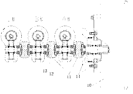
[0002] At present, for the three-position isolating switch used in fully enclosed combined electrical appliances, its closing action and opening action are through the output torque of the operating mechanism, and then through the torque output shaft of the operating mechanism and the corresponding phase shaft and adjacent The interphase transmission insulator that acts as a transmission connection between the two-phase shafts drives the three-phase moving contacts to rotate synchronously. The existing interphase transmission insulator uses insulating rubber-soaked tubes, and the transmission is connected by a shaft pin. This transmission The connection structure is generally used when the distance between the phases is large, that is to say, it can only be used when the installation space is large enough. In some special applications, the overall dimensions of the three-position isolating switch must be controlled within a small range. This requires that the distance between the phases must be reduced so that the arrangement of the three-position conductors is relatively compact to meet the requirements. However, the insulation between the phases must be ensured while reducing the distance between the phases. At present, there is no isolating switch that meets these requirements. Insulators for drive connections between phases of disconnectors

Method used


Image

  • Rotary insulator and isolating switch
  • Rotary insulator and isolating switch
  • Rotary insulator and isolating switch

Examples


Embodiment Construction

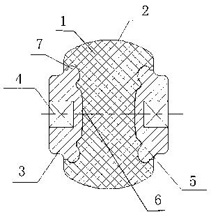
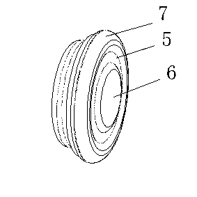
[0019] figure 1 , figure 2 Shown is an embodiment of the rotating insulator provided by the present invention. The insulator includes an insulator 1 in the form of a pie-shaped rotator, and the gyratory surface of the insulator is a smooth spherical surface 2; both ends of the insulator are fixed with connectors 3 , the connecting piece is also a revolving body, one end of which is a transmission end, and the end surface of this end is provided with a transmission hole 4 for inserting the connection end of the corresponding rotating shaft to realize torque transmission connection. The transmission hole is a square transmission hole, and the other end is a package The buried end has an extended edge 7 extending radially outward from the end surface, and the end surface 6 of the end is spherical, and an annular groove 5 is also provided on the end surface. The embedded end of the connector is embedded and fixed inside the insulator, the transmission end of the connector protru...


PUM


Abstract

The invention relates to a rotary insulator and an isolating switch. The rotary insulator comprises an insulator which is a cake-shaped revolving body; connecting pieces are fixedly arranged at both ends of the insulator; one end, facing to the insulator, of each connecting piece is wrapped and fixedly arranged inside the insulator, and one end, extending out of the insulator, of each connecting piece is a transmission end; a transmission hole in which a connecting end corresponding to a rotating shaft is inserted so as to realize torque transmission connection is formed in the end surface of each transmission end; the transmission holes at both ends are arranged coaxially; and the minimum distance between the two connecting pieces inside the insulator is not less than the striking distance of the insulator. The distance between two adjacent phases or between an operating mechanism and a corresponding phase is shortened, so that the structure of the isolating switch is more compact, the boundary dimension of the isolating switch is shortened, the isolating switch can be installed and used in a smaller space, and simultaneously the manufacturing cost of the isolating switch is also reduced.

Description

technical field [0001] The invention relates to the technical field of high-voltage switchgear, in particular to a high-voltage isolating switch and a rotating insulator which can be used for transmission connection between phases of the high-voltage isolating switch. Background technique [0002] At present, for the three-position isolating switch used in fully enclosed combined electrical appliances, its closing action and opening action are through the output torque of the operating mechanism, and then through the torque output shaft of the operating mechanism and the corresponding phase shaft and adjacent The interphase transmission insulator that acts as a transmission connection between the two-phase shafts drives the three-phase moving contacts to rotate synchronously. The existing interphase transmission insulator uses insulating rubber-soaked tubes, and the transmission is connected by a shaft pin. This transmission The connection structure is generally used when th...

Claims


Application Information

Patent Timeline
IPC IPC(8): H01H31/02
Inventor 周茂欣刘威谭传亮张丽娜李广达
Owner STATE GRID CORP OF CHINA
Learn More