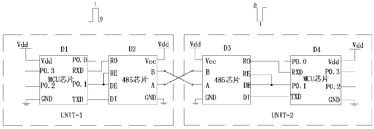
A non-polar transceiver unit and rs-485 communication circuit
A RS-485, transceiver unit technology, applied in the field of communication circuits, can solve problems affecting the efficiency and quality of construction, inability to communicate correctly, and inability to achieve, to facilitate construction, eliminate communication failures, and ensure correctness.
- Summary
- Abstract
- Description
- Claims
- Application Information
AI Technical Summary
Problems solved by technology
Method used
Image
Examples
Embodiment 1
[0032] as attached image 3 As shown, a non-polarity transceiver unit includes an RS-485 chip D3 with a communication interface A terminal and a B terminal, an MCU chip D4 capable of detecting the signal phase of its own RXD terminal, the RO terminal of the RS-485 chip D3 and the MCU chip The RXD end of D4 is connected, the DI end of the RS-485 chip D3 is connected with the TXD end of the MCU chip D4, and the P0 of the MCU chip is also connected between the RO end and the RXD end, and between the DI end and the TXD end. The non-polar logic circuit controlled by the 0 terminal is used to transmit the signal correctly when the A terminal and the B terminal of the communication interface of the RS-485 chip are positively connected, and reverse the polarity of the output signal of the RO terminal and the input signal of the DI terminal when the reverse connection is made. The correct transmission of the signal is realized, and at the same time, the RE terminal and the DE terminal ...
Embodiment 2
[0050] as attached Figure 5 As shown, a non-polar transceiver unit includes an RS-485 chip D3 with a communication port A and a B port, and an MCU chip D4 capable of detecting the signal phase of its own RXD port. The RO end of the RS-485 chip D3 is connected to the RXD end of the MCU chip D4, the DI end of the RS-485 chip D3 is connected to the TXD end of the MCU chip D4, and the RE end of the RS-485 chip D3 and the DE end are connected with the P0.1 end of the MCU chip D4. A non-polar logic circuit controlled by the P0.0 terminal of the MCU chip is also connected between the RO terminal and the RXD terminal, and between the DI terminal and the TXD terminal, to reverse the RO when the communication interface of the RS-485 chip is reversed. The output signal of the terminal and the polarity of the input signal of the DI terminal realize the correct transmission of the signal.
[0051] In this embodiment, the RE end and the DE end of the RS-485 chip D3 are all connected with...
Embodiment 3
[0067] as attached Figure 7 As shown, the nonpolar RS-485 communication circuit in this embodiment includes 2 nonpolar transceiver units as shown in embodiment 1 (according to needs, also can be more than 2), and MCU chip D1 and RS-485 chip The signal communication unit composed of D2, the MCU chip D1 and the RS-485 chip D2 are connected in the same way as in Embodiment 1 or 2. The A terminal and B terminal of the communication interface of the RS-485 chip D2 are connected to the RS-485 bus, and the two non-polarity transceiver units are also connected to the RS-485 bus. The correct sending and receiving of signals can be realized whether the A-end and B-end of the communication interface of the two RS-485 chips D3 are wired positively or negatively.
PUM
 Abstract
Description
Claims
Application Information
 - R&D
- Intellectual Property
- Life Sciences
- Materials
- Tech Scout
- Unparalleled Data Quality
- Higher Quality Content
- 60% Fewer Hallucinations
Browse by: Latest US Patents, China's latest patents, Technical Efficacy Thesaurus, Application Domain, Technology Topic, Popular Technical Reports.
© 2025 PatSnap. All rights reserved.Legal|Privacy policy|Modern Slavery Act Transparency Statement|Sitemap|About US| Contact US: help@patsnap.com


