
Low latency signaling over digital network

A digital network and digital technology, applied in the fields of electrical digital data processing, sensors, diagnosis, etc., can solve the problems of increasing the physical complexity of security and emergency information, and increasing the complexity of MRI systems, and achieve the effect of reducing cost and complexity.

Active Publication Date: 2013-07-24
KONINKLIJKE PHILIPS ELECTRONICS NV
View PDF5 Cites 2 Cited by
  • Summary
  • Abstract
  • Description
  • Claims
  • Application Information

AI Technical Summary

Problems solved by technology

While the dedicated signal lines provide a solution to these safety requirements, the increasing complexity of MRI systems increases the cost and physical complexity of implementing a backplane bus and / or signal lines to convey safety and emergency information

Method used


Image

  • Low latency signaling over digital network
  • Low latency signaling over digital network
  • Low latency signaling over digital network

Examples


Embodiment Construction

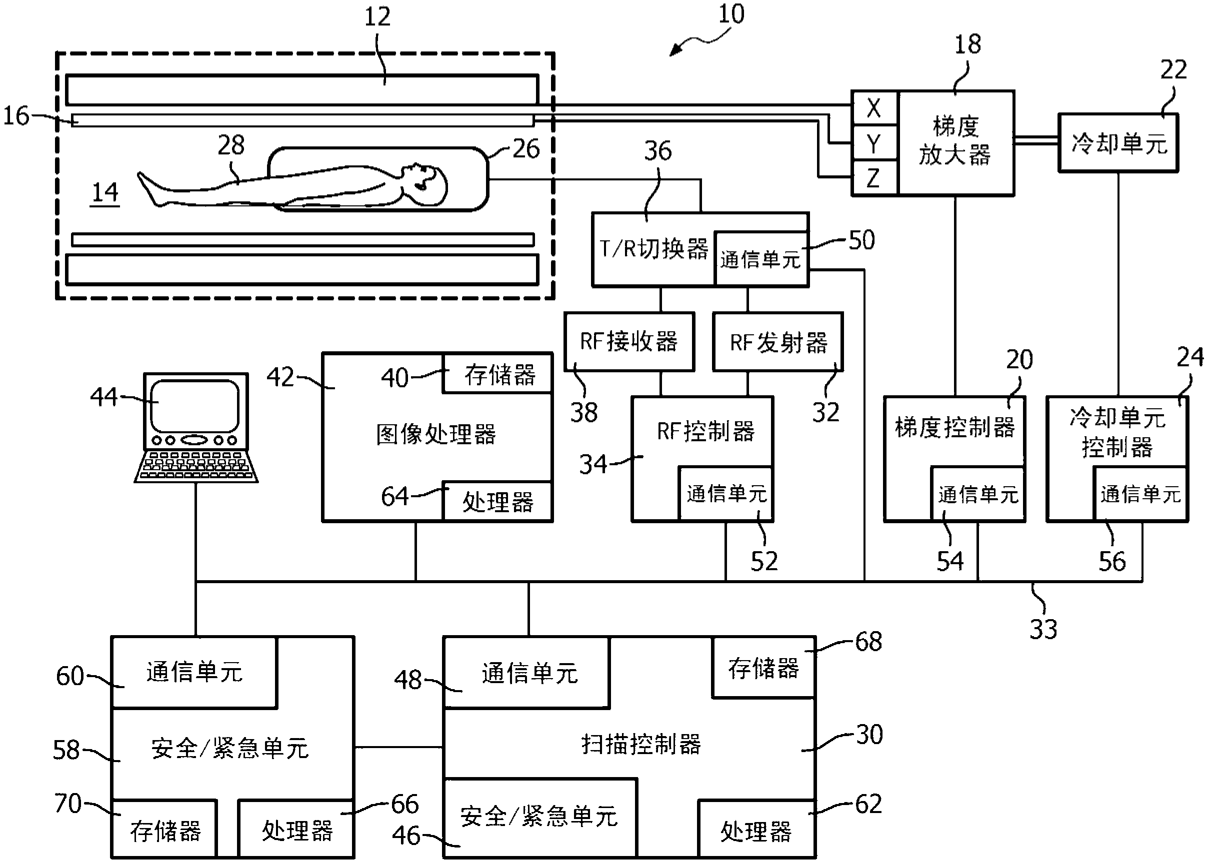
[0017] refer to figure 1 , a magnetic resonance imaging (MRI) system 10 includes a main magnet 12 that generates a spatially and temporally uniform B through an examination region 14 0 field. The main magnet 12 may be a ring-shaped or bore-shaped magnet, a C-shaped open magnet, or other designs of open magnets.

[0018] A gradient magnetic field coil 16 disposed adjacent to the main magnet 12 is used to generate an edge relative to the B 0 The magnetic field gradient along a selected axis of the magnetic field is used to spatially encode the magnetic resonance signal, to generate magnetization-destroying field gradients, and the like. The gradient magnetic field coil 16 may include coil segments configured to generate magnetic field gradients in three orthogonal directions, typically the longitudinal or z direction, the transverse or x direction, and the vertical or y-direction. A gradient amplifier unit 18 controlled by a gradient controller 20 comprises a plurality of am...


PUM


Abstract

A diagnostic imaging system includes a first controller that detects any unsafe or dangerous conditions in a diagnostic scanner and generates safety / emergency data indicative of the unsafe or dangerous conditions. A communication unit generates a safety / emergency signal from the safety / emergency data using a digital protocol and communicates the safety / emergency over a local digital network.

Description

technical field [0001] This application relates to the field of diagnostic imaging. It has particular application to, and is described with particular reference to, the communication of safety and emergency information over a digital network in a Magnetic Resonance Imaging (MRI) system. However, it should be understood that it also applies to other imaging devices, and is not necessarily limited to the aforementioned applications. Background technique [0002] Currently, magnetic resonance imaging systems use a backplane bus to communicate safety and emergency information. The backplane bus includes an array of dedicated signal lines to convey safety and emergency information to the various safety and interlock mechanisms of the MRI system. Safety and emergency information is critical in, for example, controlling the state of the RF transmit / receive switcher, but can also be applied to various other system states and to control corresponding equipment in the MRI system, in...

Claims


Application Information

Patent Timeline
Patent Type & Authority Applications(China)
IPC IPC(8): A61B5/055G06F13/38G01R33/54
CPCA61B5/0013G01R33/543A61B2560/0271A61B5/055G06F13/38G01R33/288G01R33/54G06F2213/0038
Inventor F·范利埃H·G·罗弗
Owner KONINKLIJKE PHILIPS ELECTRONICS NV
Learn More