Water displacement boat with air cavities on the bottom

A technology for planing boats and air chambers, which can be applied to ships, equipment to reduce ship motion, hydrodynamic characteristics/hydrostatic characteristics, etc., and can solve problems such as component damage, equipment efficiency reduction, and channel depth reduction.

Inactive Publication Date: 2013-07-24
MIN PROMYSHLENNOSTI I TORGOVLI ROSSIJSKOJ FEDERATSII
View PDF6 Cites 5 Cited by
  • Summary
  • Abstract
  • Description
  • Claims
  • Application Information

AI Technical Summary

Problems solved by technology

Additionally, elements that protrude beyond the base plane are vulnerable to damage if they run aground, collide with submerged material, or if the channel depth is sig

Method used


Image

  • Water displacement boat with air cavities on the bottom
  • Water displacement boat with air cavities on the bottom
  • Water displacement boat with air cavities on the bottom

Examples


Embodiment Construction

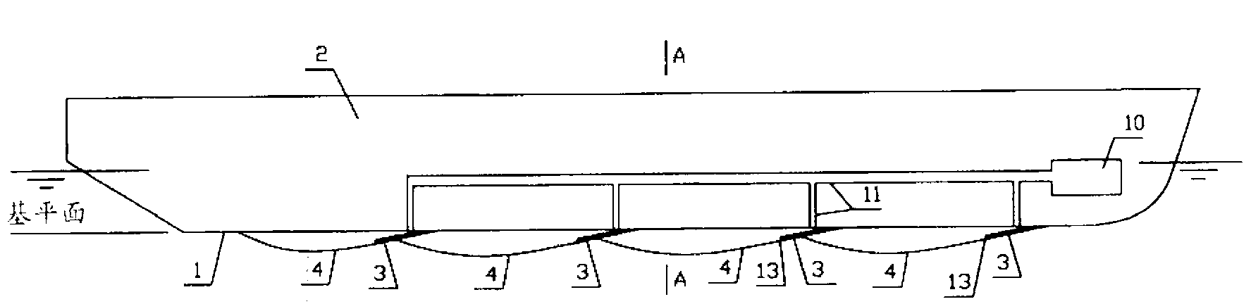
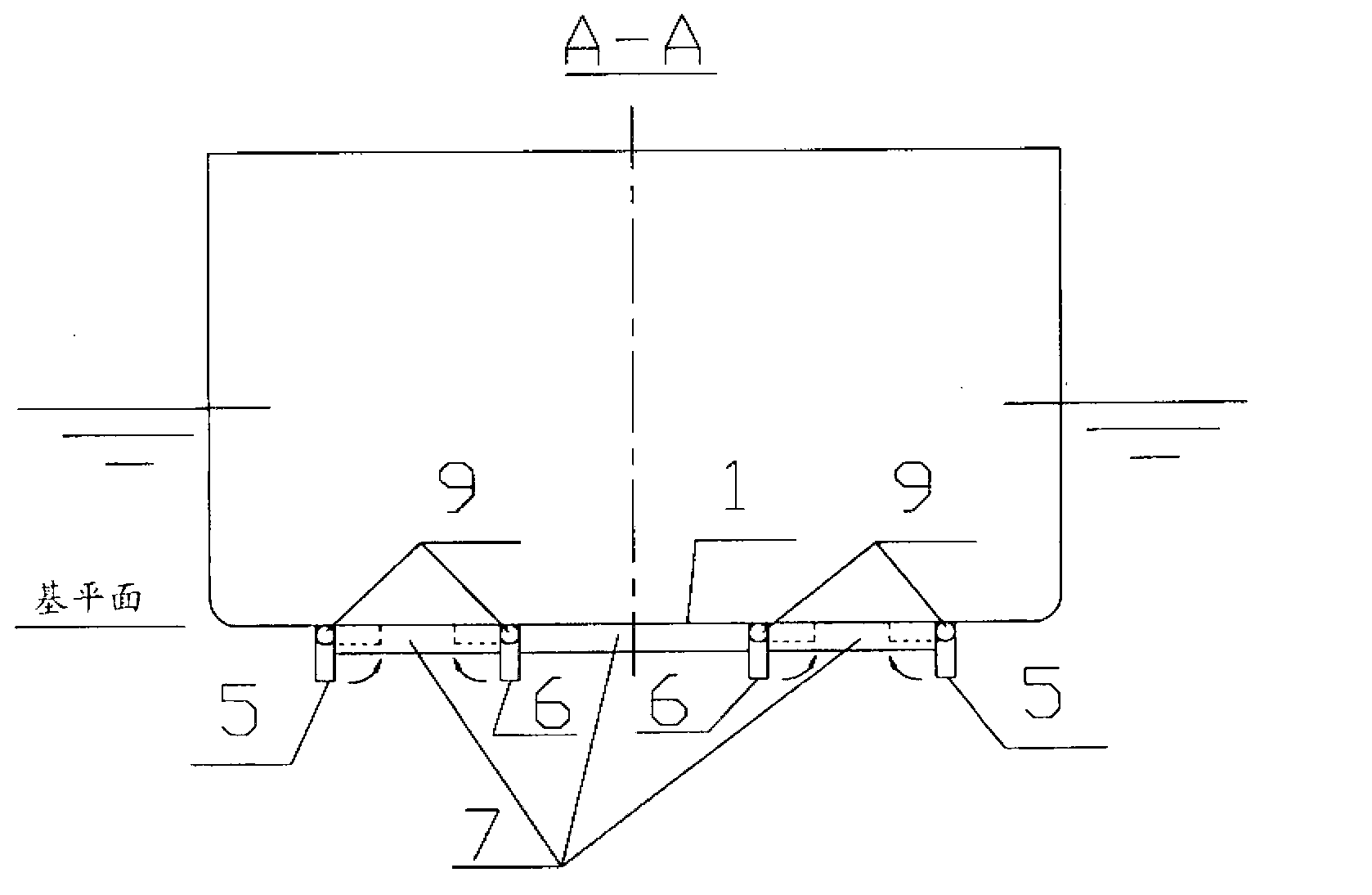
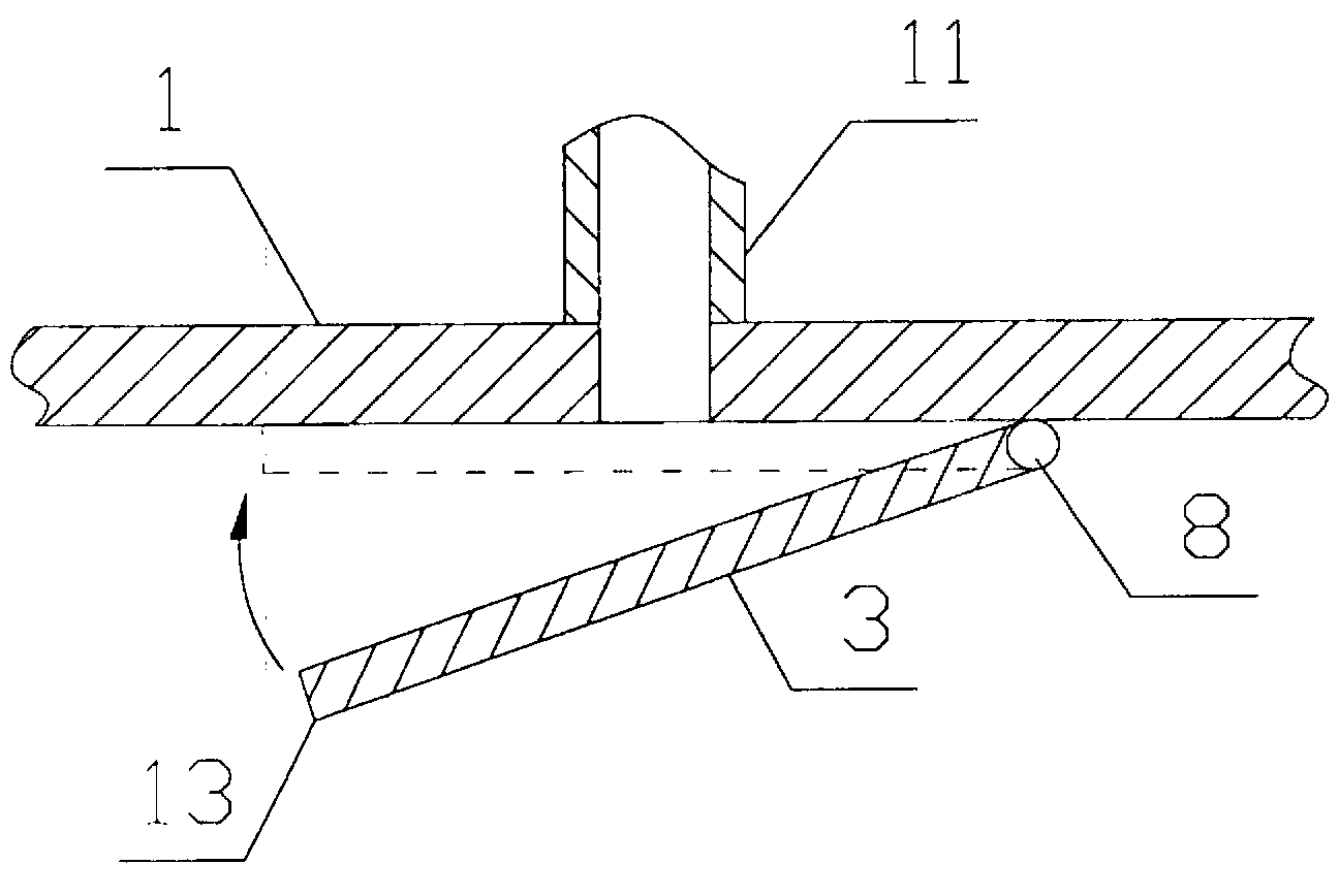
[0018] Planing craft with air chambers on the bottom (see figure 1 , 2 and 3) comprise the following units: the bottom 1 of the boat 2 is fitted with a transverse fitting 3 (ramp) which forms and holds the air chamber 4 . Longitudinal keels 5 extend from each side of the bottom 1 , which confine the formed chamber 4 and prevent the movement of air from the chamber 4 towards the sides of the vessel 2 . The height and length of the longitudinal keels 5 must be sufficient to prevent the loss of air pumped under the bottom to create and maintain the chamber. In order to increase the lateral stability of the ship and prevent the circulation of air from one side to the other, the chamber 4 is divided into several isolated longitudinal segments 7 by an intermediate longitudinal keel 6 (see figure 2 ). The transverse fittings 3 are able to retract the bottom 1 ( image 3 ). As suggested in another variant, the limiting longitudinal keels 5 and intermediate longitudinal keels 6 c...


PUM


Abstract

The invention to ship building, particularly to displacement ship with air cavities in bottom. Proposed ship is equipped with device to create air cavities under bottom including cavity-forming system made up of inclined transverse plates arranged one after another and lengthwise constricting keels arranged on bottom sides. Ship incorporates forced air feed system to create and maintain cavities behind aforesaid transverse plates. Transverses plates and lengthwise keels of said retractable system may unfold and fold to fit bottom on turning about their lengthwise axles on ship bottom. The water displacement boat with air cavities on the bottom is characterized in that operating performances are improved, designed draft of the ship is maintained, and navigation resistance of the ship on a surgy sea of notable trim is reduced.

Description

technical field [0001] The present invention relates to ship building and to the structure of a planing boat with an air chamber on the bottom which reduces hydrodynamic resistance and improves the performance of the boat. Background technique [0002] The device for creating a continuous air chamber in the bottom of the ship was granted a Soviet patent, patent number 1145587. The main element of the device is the bottom recess, which is used to accommodate a continuous air chamber with a wavy profile. This recess is limited by forward steps, side keels and stern ramps. Longitudinal keels mounted in this air chamber divide it into sections for greater lateral stability, and fittings extending through the longitudinal keel are used to form continuous chambers as the boat moves. However, this recess reduces the internal volume of the ship, which may result in the need to increase the height of the dry chord or cargo holding coaming to maintain its capacity, which in turn lea...

Claims


Application Information

Patent Timeline
IPC IPC(8): B63B1/38
CPCB63B2039/065B63B1/38Y02T70/122Y02T70/10
Inventor 亚历山大弗拉基米罗维奇·普斯托士尼尤里尼古拉耶维奇·戈尔巴乔夫伊格尼亚历山大罗维奇·梅斯恰诺夫安德烈弗拉基米罗维奇·斯韦奇科夫
Owner MIN PROMYSHLENNOSTI I TORGOVLI ROSSIJSKOJ FEDERATSII
Why Eureka
Try Eureka